


變壓器油中氣體線上監測診斷系統 – 可擴展為變壓器監測系統 (TMS)
9 gas on-line DGA expandable with add-ons to a Transformer Monitoring System (TMS) 型號:Kelman DGA 900 PLUS-
得益於多種氣體 DGA 供應商超過 15 年的經驗和超過 15,000 台設備的現場使用,DGA 900 囊括了從其前代產品中汲取的經驗和改進,帶來了改進的性能、創新的新功能、增強的用戶體驗以及更高的現場可靠性和穩定性。
雖然線上 DGA 現在被廣泛認為是評估變壓器狀況的最有效方法,但它並沒有涵蓋所有可能的問題來源。尤其對於OLTC、冷卻系統或套管等子系統,如果不加以監控,變壓器本身也會產生其它來自不同的風險來源。DGA 900 PLUS 監控系統彙整了 DGA 測量、所附加的感測器、分析模型和數據處理功能,可解決大多數常見的故障模式。這個具有成本效益的監控整合提供了有效管理和最佳利用這一重要變電站資產所必需的狀態評估工具。同時,DGA 900 PLUS很適合監控大型關鍵任務變壓器或受損變壓器,以延長其使用壽命並防止任何意外故障:
主要優勢
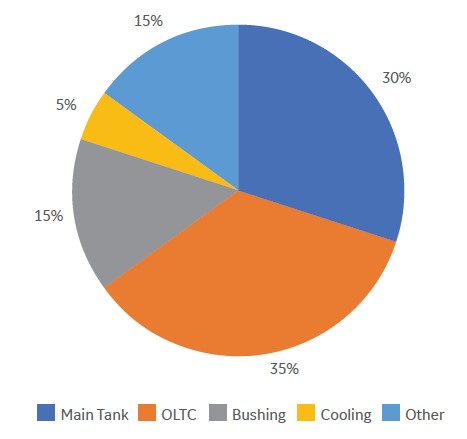
變壓器故障模式
- 模組化和可選擇的監測項目,所使用是可選擇性的標準模組功能。
- 可遠端監控了解變壓器狀況和運轉上的狀態。
- 可對數據進行關聯驗證和深入故障分析。
- 使用嵌入式網頁的人機界面和彩色螢幕進行圖形顯示。
- 與 GE 廣受讚譽的 Perception™ Fleet資產管理軟體所結合。
- 全球唯一擁有 15 年 PAS 經驗且安裝量超過 15,000 台的供應商。
絕緣油的溶解氣體分析(DGA)

絕緣油的溶解氣體分析(DGA)和濕度測量被認為是變壓器狀態評估最重要的檢測方法。在以往傳統變壓器維護手法,多樣氣體 DGA 測量受限於僅在實驗室環境,並在每一年採以不定期手動取樣分析,以輔助基於固定時間點檢的維護策略。然而,隨著全球變壓器平均使用年限的不斷增加,在每年與隔年點檢期間,發生快速老化甚至災難性故障的可能性也隨之增加,這導致許多資產所有者開始採用線上 DGA 監控,對變壓器的惡化狀況進行預防性警報和即時性多種氣體量測。
這有助於做出維護上的決策,無需前往現場進行手動絕緣油取樣。這可避免了計劃外的停機,提高了電網的可靠度,並實現了基於狀態的維護。
2000 年代初,GE最初的 Kelman™ 系列線上多種氣體 DGA 分析儀為市場帶來了光聲光譜(PAS)測量技術。現今GE 隆重推出新一代多種氣體線上 DGA 和濕度分析儀 - Kelman DGA 900。其核心是對GE經過驗證的 PAS 技術進行了改進,可提供具有實驗室挑戰性的精度和可重複性水準,且無需消耗品(載氣或校正氣體),也無需頻繁重新校正。此外,Kelman DGA 900還具有更強的演算能力和可擴展的輸入/輸出埠,可滿足未來需求並增加功能,使每台分析儀都能發展成為靈活的變壓器監測解決方案。
有了Kelman DGA 900 PLUS,變壓器問題可以在萌芽階段就被發現,從而確保儘早解決問題,達到變壓器的額定預期壽命。讓資產管理者可以有計劃地進行維護干預,縮短維護時間,降低維護成本,並減少對電網和電力用戶的影響。此外,老化資產的汰換策略可以基於可靠的健康狀況數據,而不是純粹基於變壓器的年齡。絕緣老化 + 冷卻
Kelman DGA 900 PLUS 還根據最新的 IEC®/ IEEE® 熱和濕度模型標準,結合從變壓器銘牌和測試報告中獲得的具體變壓器特性進行計算。
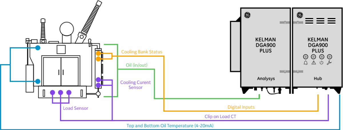
可整合的 Kelman DGA 900 PLUS 配有可選擇的輸入/輸出 (I/O) 模組卡,可便於連接其它感測器,以擴大其監測範圍。當添加這些附加裝置後,DGA 900 可以連續測量其它關鍵參數,如油溫、負載電流、油中含水量和冷卻狀態,這些參數是 DGA 信息的補充。
這些模型將原始數據轉換為額外的有用信息,並以每 10 分鐘監測一次變壓器絕緣系統的狀態並確定其長期老化曲線。這些信息還能幫助資產管理者做出重要的營運決策,尤其是通過計算動態負載能力,安全地對老化變壓器進行過載。所有模型的目的都是幫助有效利用變壓器的使用壽命(這取決於其絕緣系統的狀態),並得出最佳運行曲線,以最大限度地提高運轉效率。有載分接頭切換器 (OLTC)
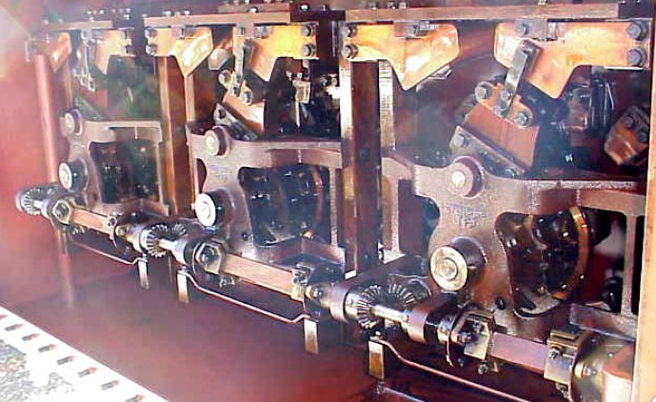
典型的線上有載分接頭切換器 (OLTC) 有載分接頭切換器 (OLTC)是一種複雜的機械裝置,其運動組件會隨著時間的推移而磨損,這是因為它們會切換電流(觸點磨損)和切換次數(機械磨損)。有載分接頭切換器每天可以工作很多次,每個切換器都要切換數千安培的電流,有時還會過度使用一組有限的觸點。這種重複使用意味著 OLTC 需要通過檢查、更換和翻新進行仔細關注。
通過監測當前位置、各位置的切換器操作次數和所累計切換器電流負載,可以估算出觸點的磨損程度。此外,還可利用 OLTC 驅動馬達的電流消耗來檢測位置切換的難度是否增加。
最後,觸點上的積碳會導致電弧增加,使有裝有載分接頭切換器隔室內的油溫升高,因此可以通過主油箱的油溫差來檢測。通過監測這些附加參數,可以對這一關鍵機電組件進行基於狀態的維護,從而避免有載分接頭切換器故障以及通常並不嚴重的隨之而來的干擾。套管監測
套管故障在變電站事故中佔很大比例,這些事故造成了嚴重而昂貴的損失,有時甚至會導致人員死亡。過去曾採用預防性維護、提前汰換套管和定期停電測試來解決這一問題。監測變壓器套管至關重要,因為由於線路電壓和電流的熱效應,套管始終處於高應力下。同時,製造過程中產生的細微裂紋、老化導致的機械強度下降、反覆的熱循環(負載+日曬)、污染和外部閃絡對瓷的侵蝕、絕緣油中的油泥和水分,以及為了降低成本、減小尺寸和重量而使新套管更接近設計極限,都會進一步加劇這些應力。
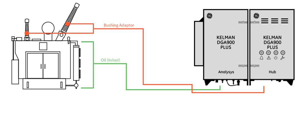
具套管監測功能的 Kelman DGA 900 PLUS 是一個整合性的線上監控系統,可連續監測多達 6 個套管(3 個高壓和 3 個低壓)的狀態。它使用定制的套管轉接器(專為每種套管類型而設計)。
它連續測量電容 C1 相對於原始銘牌值的變化。它還能測量與原始銘牌值相比的相對功率因數(Tan Delta)變化。如果來自比壓器的參考電壓(相對地)信息可用,則可以計算並顯示套管感應的實際功率因數。
它還能測量與原始銘牌值相比的相對功率因數(Tan Delta)變化。如果有電壓互感器的參考電壓(相地)信息,則可以計算並顯示套管感應的實際功率因數。這提供了與停電下測試類似的信息,這對維護上非常有幫助。
局部放電檢測 ( PD )
局部放電是指固體或液體電氣絕緣系統的一小部分在高壓應力作用下發生局部擊穿,無法完全彌合兩個導體之間的空間。固體電介質上的局部放電會導致絕緣系統的局部逐漸腐蝕,最終導致關鍵絕緣失效。
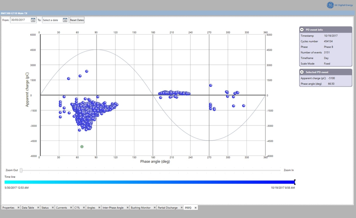
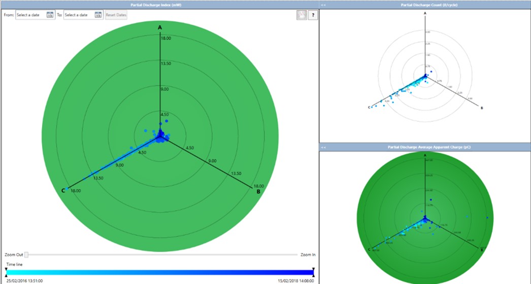
通過使用相同的套管轉接器,DGA 900 PLUS 還能測量高頻信號以監控 PD 活動,從而為變壓器的主油箱提供更高級別的保護。所有PD 脈衝的振幅將都被記錄下來,用於計算 PD 活動的總體測量值。有幾種方法可用於區分內部局部放電和外部雜訊(電暈放電)。 BMT 330 機型還提供局部放電相位分析法 (Phase Resolve Partial Discharge;PRPD)的診斷功能。
利用後台分析引擎產生的監控數據&視覺化圖形,提供清晰的診斷趨勢 -
MEASUREMENTS Technology
Automated head-space gas extraction. Photo-acoustic spectroscopy (PAS) gas measurement. Thin film capacitive moisture sensor. Immersed fiber optic oxygen sensor. Frequency Configurable from once per hour to once every 4 weeks.
Faster sampling automatically triggered upon alert level reached.
"Rapid Mode" provides a rapid indication of the evolution of the gasses indicated below in ~30 minutes.Range
LDL UDL Accuracy* Repeatability Response Time*** Rapid Mode Hydrogen (H₂) 5 5,000 ppm ± LDL or ±5 % < 3 % > 90 % • Carb. Monox. (CO) 1 50,000 ppm ± LDL or ±3 % < 2 % > 95 % • Methane (CH₄) 2 50,000 ppm ± LDL or ±3 % < 2 % > 95 % Acetylene (C₂H₂) 0.5 50,000 ppm ± LDL or ±3 % < 2 % > 95 % • Ethylene (C₂H₄) 1 50,000 ppm ± LDL or ±3 % < 2 % > 95 % Carb. Diox. (CO₂) 20 50,000 ppm ± LDL or ±3 % < 3 % > 95 % • Ethane (C₂H6) 1 50,000 ppm ± LDL or ±3 % < 2 % > 95 % Oxygen (O₂) 100 50,000 ppm ± LDL or ±5 % < 2 % • Nitrogen (N₂) ** 10,000 100,000 ppm ± LDL or ±15 % Moisture (H₂O) 0 100 % RS (in ppm) ± 3 % ppm < 3 % • *whichever is greater. Accuracy quoted is the accuracy of the detectors during calibration. Gas-in-oil measurement may be affected by oil type and condition.
Repeatability as measured from final production test data.
** N₂ value is calculated and available on free-breathing transformers only.
*** Time Response (typical): % of value after 1 measurement cycle.FEATURES Display
4 x Sunlight visible LED arrays
Backlit 7” inch color resistive touch screen (800 x 480)
Embedded secure webserver (https)Analogue Input 1 x Standard for split core load CT sensor Digital Output
6 x Standard customer programmable dry contact relays (type C, SPDT), NO/NC, 10A @250Vac resistive load, 8A @30Vdc resistive load
1 x Standard service alarm relay
1 x Standard watchdog relayDigital Communications / Protocols 1 x Modbus® over RS485 / TCP/IP as standard
1 x DNP3.0 TCP/IP as standard
1 x Standard 1Gb Ethernet (RJ45)
Option: DNP3.0 over RS485 or TCP/IP
Option: IEC 61850 Edition 2
Option: ST/SC Multi-mode fiber converters
Option: GPRS/UMTS/HSPA+ modemADD-ONS † Pack 1 – Thermal Models Standard: 3 x 5A split core load CT sensors
Standard: 2 x Magnetic mounted temperature sensorPack 2 – Cooling Monitoring
Standard: 4 x 30A split core CT sensors
All sensors supplied as standard, no customization.
Note: Interdependency: Pack 2 requires Pack 1Pack 3 – OLTC Monitoring Standard: Active power consumption sensor
Standard: 2 x Magnetic mounted temperature sensor
Standard: 4 – 20mA or Resistive OLTC position input (sensor not supplied)Pack 4 – Bushing Monitoring 3 Phase Transformers Up to 6 x Bushing adaptors ordered separately
Standard: Bushing HV (3 Bushings)
Option: Bushings HV & LV (6 Bushings) ††
All sensors supplied unless notedMECHANICAL Analysis Unit Hub Unit Dimensions 600 x 484 x 330 mm 600 x 380 x 330 mm 23.6 x 19.1 x 13.0 in 23.6 x 15.0 x 13.0 in Weight 33.4 kg / 73.6 lb 18.5 kg / 40.8 lb POWER REQUIREMENTS AC Nominal 100-240 Vac (Range 85-264), 4A
DC Nominal 100-250 Vdc (Range 90-300)OPTIONS Mounting stand and Sun canopy
Longer umbilical cable between unitsENVIRONMENT Operating Conditions
mbient temperature:-40 °C to +55 °C (-40 °F to +131 °F)
Ambient humidity:0-95 % RH, non-condensing
Oil temp at valve††:-20 °C to +120 °C (-4 °F to +248 °F)Enclosure IP56 certified
Standard: Powder coated marine grade 2 mm aluminium (RAL9002)
Option: Unpainted 316 Stainless Steel
†Select maximum 3 out of 4 add-on packs
††Option for monitoring up to 9 x Bushings available soon
†††Based on testing carried out using Voltesso™ 35 mineral oil, over a ¼” pipe run of 10 metres or less from oil supply or return valve to monitor connection point
and on transformer oil supply valve volumes of 200 ml or less. For oil temperatures colder than -20 ºC GE recommends the use of heat trace cabling on piping -
Benefiting from over 15 years of multigas DGA vendor experience and over 15,000 devices in the field, the DGA 900 encapsulates learnings and improvements derived from its predecessors to bring improved performance, innovative new features, enhanced user experience and increased field reliability and robustness.
While on-line DGA is now widely accepted as the most effective method of assessing the condition of a transformer, it does not cover all the possible sources of issues. Subsystems like the tap changer, the cooling system or the bushings can generate their own problems if they are left unmonitored. The DGA 900 PLUS monitoring system integrates DGA measurement, additional sensors, analysis models and data handling features to address the majority of prevalent failure modes. This cost-effective package provides the condition assessment tools essential for the effective management and optimal utilization of this critical sub-station asset. It is most suited for monitoring large, mission critical transformers or compromised transformers with a view to extending their life and preventing any unexpected failure:
Key BenefitsTransformer Failure Modes
- Modular and retrofittable architecture using selectable standard add-on cards
- Provides extensive remote insight into transformer condition and safe operation
- Enables correlation of data for validation and in-depth fault analysis
- Graphical presentation using built-in web-page based HMI and local color screen
- Full integration with GE’s acclaimed Perception™ Fleet asset management software
- From the only vendor with 15 years PAS experience and installed base of >15,000 units
Dissolved Gas Analysis (DGA)Dissolved Gas Analysis (DGA) and moisture measurements of insulating fluids are recognized as the most important tests for condition assessment of transformers. In previous years, multi-gas DGA was traditionally confined to a laboratory environment, with infrequent yearly off-line manual sampling aiding time-based maintenance strategies.
However, as the global average age of transformers continued to rise, the possibility of rapid aging and even catastrophic failure between off-line tests also increased, leading many asset owners to adopt on-line DGA monitoring to provides remote alert and multi-gas diagnostic of deteriorating transformer condition.
This facilitated operational decisions without needing to go to site for manual oil sampling. It avoided unplanned outages, increased network reliability and enabled the move to condition-based maintenance.
In the early 2000’s, GE’s original Kelman™ range of on-line multi-gas DGA analyzers brought Photo-Acoustic Spectroscopy (PAS) measurement technology to the market. GE is now proud to introduce the Kelman DGA 900, its next-generation multi-gas on-line DGA and moisture analyzer. At its heart lies an evolved implementation of GE’s proven PAS technology, providing laboratory challenging levels of precision and repeatability with no consumables (carrier or calibration gases) and no need for frequent re-calibration. It also has enhanced computing power and scalable I/Os for future proofing and adding functionalities to grow each analyzer into a flexible transformer monitoring solution.
Transformer issues can now be detected in their infancy, making sure that they are fixed early so that the nominal expected life of the transformer can be achieved. Maintenance interventions can now be planned, reducing their length and their cost and causing less disruption to the network and customers. In addition, aging asset replacement strategies can be anchored on hard health condition data and not purely based on the age of the transformer.
Insulation + Cooling
Kelman DGA 900 PLUS further incorporates on-board calculations based on the very latest IEC®/ IEEE® thermal and moisture models standards and computed from the specific transformer characteristics obtained from the name-plate and test reports of the transformer.
The integrated Kelman DGA 900 PLUS comes with optional Input/Output (I/O) cards so that additional sensors can be attached to increase its measurement scope. With this add-on, the DGA 900 can continuously measures other critical parameters such as oil temperatures, load current, water content in oil, and cooling status which are complementary to the DGA information.
These models convert raw data into additional intelligent information to monitor the state of the transformer’s insulating system every 10 minutes and determine its long term aging profile. This information can also assist system operators in making critical operational decisions, particularly when it comes to safely overloading aging transformers by calculating the dynamic loading capacity. The aim of all the models is to aid in optimizing the transformer’s life (which is dictated by the state of its insulating system) and in deriving the optimum operating profile to maximize operational effectiveness.
OLTC
A typical On-Line Tap Changer On-Line Tap Changers (OLTCs) are complex mechanical devices with moving parts that wear over time due to the current they switch (contact wear) and the number of switches they perform (mechanical wear). An OLTC can operate many times a day, switching thousands of amps on each switch and sometimes over-using a limited set of contacts. This repeated use means that OLTCs require careful attention through inspection, replacement and refurbishment.
By monitoring the current position, the number of switching operations by position and the cumulated switched current load by position, an estimation of the contact wear can be obtained. In addition, the current consumption of the OLTC drive motor can be used to detect an increased difficulty in switching positions.
Finally, coking of the contacts will lead to increased arcing, to an elevated oil temperature in the OLTC compartment and thus can be detected by an oil temperature delta to the main tank. By monitoring these additional parameters, Condition Based Maintenance can be used on this key electro-mechanical component and an OLTC failure can be avoided, along with its usually not insignificant ensuing disruptions.
Bushing
Bushing failures account for a large proportion of substation events that result in severe and costly damages and unfortunately even sometimes fatalities. Preventive maintenance, early bushing replacement and regular off-line testing have been employed to address this issue in the past. Monitoring transformer bushings is critical because bushings are constantly under high stress due to the line voltage and heat effect of the current flow. These stresses can be further aggravated by the presence of micro cracks from manufacturing, loss of mechanical strength due to aging, repeated thermal cycling (load + sun), pollution and external flashover eroding the porcelain, sludge and moisture in the insulating oil, and by the fact that new bushings have been made closer to design limits in order to reduce cost, size and weight.
The Kelman DGA 900 PLUS with bushing monitoring is an integrated on-line system that continuously monitors the condition of up to 6 bushings (3x HV and 3x LV). It uses custom bushing adapters (specifically designed for each bushing type).
It continuously measures the change in Capacitance C1 compared to the original nameplate value. It also measures the relative Power Factor (Tan Delta) change compared to the original nameplate value. If the reference voltage from a voltage transformer (phase to ground) information is available, then the real PF induced by the bushing can be calculated and displayed. This provides information similar to that obtained during off-line tests.
Partial Discharge Detection
PD is a localized breakdown of a small portion of a solid or fluid electrical insulation system that is under high voltage stress, which does not completely bridge the space between two conductors. PD on solid dielectrics results in localized gradual erosion of the insulation system that eventually leads to failure of critical insulation.
Using the same bushing adaptors, the DGA 900 PLUS offers the added advantage of measuring high frequency signals in order to monitor PD activity, giving an added level of protection for the main tank of the transformer. The amplitude of the PD pulses are recorded and used to calculate an overall measure of PD activity. Several methods are used to discriminate between internal PD and external noise (corona discharge). The BMT 330 also provides Partial Discharge Phase Resolve (PDPR) diagnostics.
Graphical Visualisation of the monitoring data generated using the backend analytical engine, provides clear diagnostic trends. -
MEASUREMENTS Technology
Automated head-space gas extraction. Photo-acoustic spectroscopy (PAS) gas measurement. Thin film capacitive moisture sensor. Immersed fiber optic oxygen sensor. Frequency Configurable from once per hour to once every 4 weeks.
Faster sampling automatically triggered upon alert level reached.
"Rapid Mode" provides a rapid indication of the evolution of the gasses indicated below in ~30 minutes.Range
LDL UDL Accuracy* Repeatability Response Time*** Rapid Mode Hydrogen (H₂) 5 5,000 ppm ± LDL or ±5 % < 3 % > 90 % • Carb. Monox. (CO) 1 50,000 ppm ± LDL or ±3 % < 2 % > 95 % • Methane (CH₄) 2 50,000 ppm ± LDL or ±3 % < 2 % > 95 % Acetylene (C₂H₂) 0.5 50,000 ppm ± LDL or ±3 % < 2 % > 95 % • Ethylene (C₂H₄) 1 50,000 ppm ± LDL or ±3 % < 2 % > 95 % Carb. Diox. (CO₂) 20 50,000 ppm ± LDL or ±3 % < 3 % > 95 % • Ethane (C₂H6) 1 50,000 ppm ± LDL or ±3 % < 2 % > 95 % Oxygen (O₂) 100 50,000 ppm ± LDL or ±5 % < 2 % • Nitrogen (N₂) ** 10,000 100,000 ppm ± LDL or ±15 % Moisture (H₂O) 0 100 % RS (in ppm) ± 3 % ppm < 3 % • *whichever is greater. Accuracy quoted is the accuracy of the detectors during calibration. Gas-in-oil measurement may be affected by oil type and condition.
Repeatability as measured from final production test data.
** N₂ value is calculated and available on free-breathing transformers only.
*** Time Response (typical): % of value after 1 measurement cycle.FEATURES Display
4 x Sunlight visible LED arrays
Backlit 7” inch color resistive touch screen (800 x 480)
Embedded secure webserver (https)Analogue Input 1 x Standard for split core load CT sensor Digital Output
6 x Standard customer programmable dry contact relays (type C, SPDT), NO/NC, 10A @250Vac resistive load, 8A @30Vdc resistive load
1 x Standard service alarm relay
1 x Standard watchdog relayDigital Communications / Protocols 1 x Modbus® over RS485 / TCP/IP as standard
1 x DNP3.0 TCP/IP as standard
1 x Standard 1Gb Ethernet (RJ45)
Option: DNP3.0 over RS485 or TCP/IP
Option: IEC 61850 Edition 2
Option: ST/SC Multi-mode fiber converters
Option: GPRS/UMTS/HSPA+ modemADD-ONS † Pack 1 – Thermal Models Standard: 3 x 5A split core load CT sensors
Standard: 2 x Magnetic mounted temperature sensorPack 2 – Cooling Monitoring
Standard: 4 x 30A split core CT sensors
All sensors supplied as standard, no customization.
Note: Interdependency: Pack 2 requires Pack 1Pack 3 – OLTC Monitoring Standard: Active power consumption sensor
Standard: 2 x Magnetic mounted temperature sensor
Standard: 4 – 20mA or Resistive OLTC position input (sensor not supplied)Pack 4 – Bushing Monitoring 3 Phase Transformers Up to 6 x Bushing adaptors ordered separately
Standard: Bushing HV (3 Bushings)
Option: Bushings HV & LV (6 Bushings) ††
All sensors supplied unless notedMECHANICAL Analysis Unit Hub Unit Dimensions 600 x 484 x 330 mm 600 x 380 x 330 mm 23.6 x 19.1 x 13.0 in 23.6 x 15.0 x 13.0 in Weight 33.4 kg / 73.6 lb 18.5 kg / 40.8 lb POWER REQUIREMENTS AC Nominal 100-240 Vac (Range 85-264), 4A
DC Nominal 100-250 Vdc (Range 90-300)OPTIONS Mounting stand and Sun canopy
Longer umbilical cable between unitsENVIRONMENT Operating Conditions
mbient temperature:-40 °C to +55 °C (-40 °F to +131 °F)
Ambient humidity:0-95 % RH, non-condensing
Oil temp at valve††:-20 °C to +120 °C (-4 °F to +248 °F)Enclosure IP56 certified
Standard: Powder coated marine grade 2 mm aluminium (RAL9002)
Option: Unpainted 316 Stainless Steel
†Select maximum 3 out of 4 add-on packs
††Option for monitoring up to 9 x Bushings available soon
†††Based on testing carried out using Voltesso™ 35 mineral oil, over a ¼” pipe run of 10 metres or less from oil supply or return valve to monitor connection point
and on transformer oil supply valve volumes of 200 ml or less. For oil temperatures colder than -20 ºC GE recommends the use of heat trace cabling on piping