


-
 micrux
-
 AARONIA AG
-
 ADASH
ADASH
-
 Amptek
-
 AOiP
AOiP
-
 AstroNova
-
 AWSensors
-
 Automatic Research
-
 BASI
BASI
-
 BRS
BRS
-
 BWB Technologies
-
 Cmc
Cmc
-
 CTRL
CTRL
-
 CALMET
-
 CHECKLINE
-
 Coxem
Coxem
-
 C-Tech
-
 DV Power
-
 DANATRONICS
-
 ECH
ECH
-
 Elsys
Elsys
-
 Enervac
-
 Enapter
-
 ELVEFLOW
-
 EA Technology
-
 EL-CELL
-
 ENERGY SUPPORT
-
 Electrothermal
-
 FASTEC
-
 GE
GE
-
 GMW
GMW
-
 Gaskatel
-
 GIUSSANI
-
 Globecore
-
 GREENLIGHT
-
 GRZ
GRZ
-
 HTW
HTW
-
 HIGH SENSE SOLUTIONSHTW
-
 HUBER
HUBER
-
 Labnics
-
 Ida
Ida
-
 LIQUID
-
 Instytut Fotonowy
-
 KEHUA TECH
-
 JGG
JGG
-
 HVPD
HVPD
-
 Jenway
-
 Jacomex
-
 IVIUM
IVIUM
-
 ndb
ndb
-
 OZM
OZM
-
 Redoxme
-
 Serstech
-
 SATIR
SATIR
-
 VacCoat
-
 Zurich
- micrux
- AARONIA AG
- ADASH
- Amptek
- AOiP
- AstroNova
- AWSensors
- Automatic Research
- BASI
- BRS
- BWB Technologies
- Cmc
- CTRL
- CALMET
- CHECKLINE
- Coxem
- C-Tech
- DV Power
- DANATRONICS
- ECH
- Elsys
- Enervac
- Enapter
- ELVEFLOW
- EA Technology
- EL-CELL
- ENERGY SUPPORT
- Electrothermal
- FASTEC
- GE
- GMW
- Gaskatel
- GIUSSANI
- Globecore
- GREENLIGHT
- GRZ
- HTW
- HIGH SENSE SOLUTIONSHTW
- HUBER
- Labnics
- Ida
- LIQUID
- Instytut Fotonowy
- KEHUA TECH
- JGG
- HVPD
- Jenway
- Jacomex
- IVIUM
- ndb
- OZM
- Redoxme
- Serstech
- SATIR
- VacCoat
- Zurich

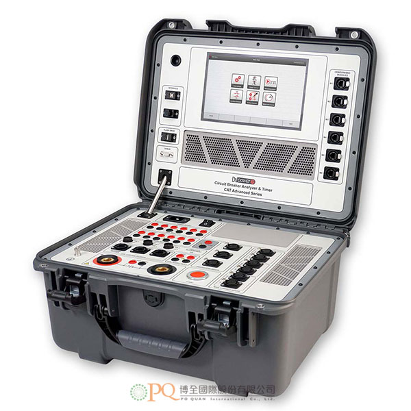
斷路器開關動作時間測定器
Circuit Breaker Analyzer & Timer 型號:CAT500 series-
CAT500 總結了DV POWER過去 15 年在斷路器測試設備設計方面的所有經驗和知識。CAT500 具有一些獨特的測試功能,大大節省了對各類中/高壓斷路器進行狀態評估所需的時間。
特點 :- 使用CAT 模組,在 BSG 條件下同時測量多達 12 個主接點的動作時間、靜態電阻和動態電阻。
- 透由一次性的電纜連接和同時測量節省測試時間。
- 動作時間、作動狀態和振動量測。
- 10.1" 彩色觸控圖形顯示幕 ,便於控制測試設備和分析結果。
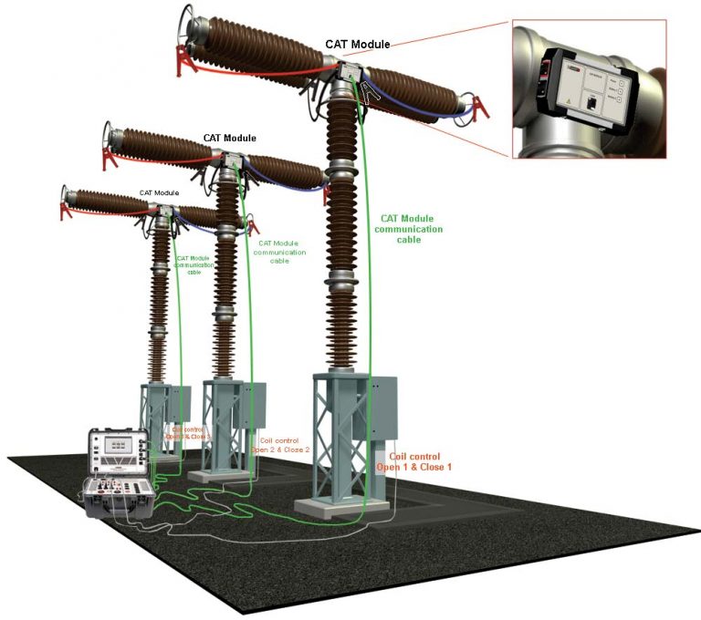
CAT 模組可測量兩端接地 (BSG) 的 AIS(空氣絕緣變電站)斷路器的主接點的動作時間、靜態和動態電阻。
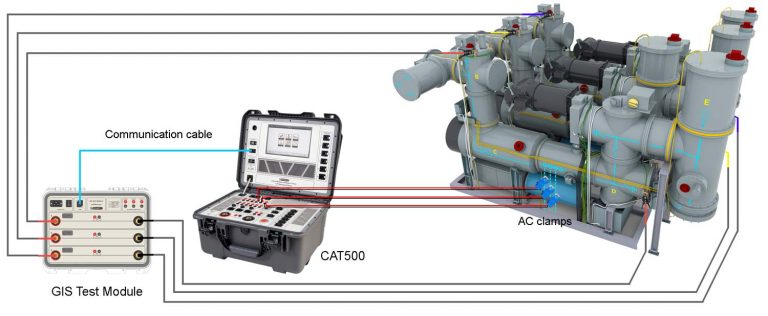
對於兩端接地的GIS 斷路器進行動作時間測量,CAT500適用於測試要求最苛刻的條件下,例如單極操作的GIS CB,其極板外殼電阻非常低,或者CT 不能夾住在測試接入點之間的測量電路中。
GIS 測試模組是由三個隔離的基於電池的電源組成,用於為單極控制斷路器的每個極提供高電流。
提供測試電流範圍為每極 400~500 A(取決於電池充電狀態和測試電路的電阻)。
代替測量 CT 二次側電流訊號的變化(當其位於接地開關電路之外時),將對所內電源監視一次側注入電流的變化。
-
CAT Module
• Number of channels: 2
• Battery Li-Po: 2 200 mAh, 7.4 V
• Max current per channel: 100 A DC
• Static resistance range: 0,1μΩ – 3 000 mΩ
• Dynamic contact res. range: 10 μΩ – 200 mΩ
• Maximum sample rate: 40 kHz
• Minimum resolution: 25 μs
• Communication: digital
Coil driver
• Number of channels: 6 (3 open and 3 close coil)
• 6 separate outputs for coil triggering
• Driver characteristics: 300 V DC max, 35 A DC max
• Electronic drivers: it provides superior timing control
• Overcurrent and overvoltage protection
• Coil supply inputs for open and close coil:
300 V DC max, 35 A DC maxMain contact inputs
• Number of contact inputs: up to 12 (3 x 4),
4 per phase, depending on the model
• Each channel detects main and pre-insertion resistor contacts.- Closed ≤ 10 Ω,
- Resistor contacts range 10 Ω to 5 kΩ,
- Open ≥ 5 kΩ
- Open circuit voltage: 20 V DC
- Short circuit current 50 mA
pre-insertion resistors
Breaker operation
• Close (C)
• Open (O)
• Close-Open (C-O)
• Open-Close (O-C)
• Open-Close-Open (O-C-O)
• First trip test
User can select any desired test sequenceTime measurement
Time measurement resolution:
• 0.025 ms for 1 s test duration (sampling rate 40 kHz)
• 0,1 ms for 2 s test duration (sampling rate 10 kHz)
• 1 ms for 20 s test duration (sampling rate 1 kHz)
• 10 ms for 200 s test duration (sampling rate100 Hz)
Time accuracy ±0,05% of the reading ± resolutionCurrent measurement
• Current measurement for Open and Close coil, 6 channels, Hall-Effect sensor
• Range ±35 A AC/DC to 5 kHz
• Accuracy ± (0,5 % rdg + 0,1 % FS)
• Graphic presentation: currents waveform is displayed with resolution of 0,1msAuxiliary inputs
• Number of channels: 6, galvanically isolated
• User selectable: dry or wet
• Contact sensing (dry): Open circuit voltage 24 V DC,
Short circuit current 5 mA
• Voltage sensing (wet): Working voltage 300 V DC, 250 V AC
Low activation mode ± 5 V
High activation mode ±10 V
• Overcurrent and overvoltage protectionCoil resistance measurement
• 3 coils simultaneously (Open or Close)
• Measuring range / Resolution
1 Ω - 99,9 Ω / 0,1 Ω
100 Ω – 999 Ω / 1 Ω
• Typical accuracy ± (0,5 % rdg + 0,5 % FS)Universal transducer inputs
• 3 digital travel transducer channels
Digital rotary transducers: 2500ppr
• 3 analog travel transducer channels
• Analog transducer input measurement resolution: 16 bit.
• Internal supply for linear transducer: 5 V DCTime measurement triggers
• External trigger: 2 channels (Open 1 & Close 1), input voltage: 10 V – 300 V AC/DC
• Coil currents: threshold level user selectable
• Auxiliary inputs
• Analog inputs: threshold level user selectable
Printer (optional)
• Thermal printer
• Graphic and numeric printout
• Paper width 112 mm / 4.4 in
• Excludes Minimum trip voltage module option
The print density is guaranteed within range: 5°C to 40°C, 20 to 85% relative humidity, non-condensingAnalog inputs
• 6 channels – Coil current measurement
• 6 Voltage channels, each channel has four measurement ranges: ±1 V, ±5 V, ±60 V and ±300 V AC/DC
The analog inputs are isolated with respect to all other circuits
Minimum trip voltage module (optional)
• Operating voltage: 10V – 300 V DC
• Adjustment step: 1 V
• Excludes built-in thermal printer optionVibration channels inputs
Intended for circuit breaker vibrations measurement
• 3 channels – for vibration monitoring sensors
Dimensions and weight
• Dimensions (L x W x H):
505 mm x 409 mm x 257 mm
19.9 in x 16.1 in x 10.1 in
• Weight: from 15,5 kg (34.1 lbs) up to 17 kg (37.4 lbs) depending on built-in featuresGIS channels inputs
Intended for BSG timing measurement feature of GIS (Gas Insulated Substation) circuit breakers
• 3 channel inputs for AC current clamps
DC output
• 24 V voltage supply for current clamps
Mains power supply
• Connection according to IEC/EN60320-1;
UL498, CSA 22.2
• Mains supply: 90 V - 264 V AC
• Frequency: 50/60 Hz
• Input power:
o 250 VA (without use of Micro Ohmmeter)
o 1900 VA (with use of Micro Ohmmeter 200 A)
o 3900 VA (with use of Micro Ohmmeter 500 A)Static resistance measurement
• Built-in Micro Ohmmeter (200 A or 500 A)
• Current range 5 A – 200 A / 500 A
• Max. load voltage 6,2 V
• Resistance range 0,1 μΩ - 999,9 mΩ
• Resolution 0,1 μΩ
• Accuracy ± (0,1 % rdg + 0,1 % FS)
Dynamic resistance measurement
• Voltage and current measuring channels
• DRM sampling rate 40 kHz (0.025 ms time
resolution)
• Resolution 16 bit
• Breaker operations available for DRM test:
o Open (O)
o Close (C)
o O – C (auto reclose)
o C – O (make brake)
o O-COApplicable Standards
• Installation/overvoltage: category II
• Pollution: degree 2
• Safety: LVD 2014/35/EU (CE Conform)
Standard EN 61010-1
• EMC: Directive 2014/30/EU (CE Conform)
Standard EN 61326-1:2006
• CAN/CSA-C22.2 No. 61010-1
Environmental conditions
• Operating temperature: -10 ºC - +55 ºC / 14 ºF - +131 ºF
• Storage & transportation: -40 ºC - +70ºC / -40 ºF - +158 ºF
• Humidity 0 % - 95 % relative humidity, non-condensingAll specifications herein are valid at ambient temperature of + 25 °C and standard accessories.
Specifications are subject to change without notice. -
CAT500 summarizes all our experience and knowledge in the design of circuit breaker testing equipment for the past 15 years.CAT500 introduces some unique testing features and significantly saves the time required for condition assessment of all types of medium- and high voltage circuit breakers.
Features :
- Simultaneous timing, static resistance, and dynamic resistance measurement on up to 12 main contacts chambers under BSG conditions by use of CAT modules.
- Saves testing time by single cable connection and simultaneous measurement.
- Timing, motion, and vibrations measurement.
- Minimum trip voltage (MTV) test.
- Graphical 10.1” touch-screen color display provides easy control of the test device and results analysis.
CAT Modules provide measurement of main arcing contacts timing, static and dynamic resistance of AIS (Air Insulated Substation) circuit breakers with both sides grounded (BSG).
Timing measurements on a GIS breaker with both sides grounded is applicable for the most demanding cases for testing such as single-pole operated GIS CB which has a very low resistance of pole’s enclosures or where CT cannot be included in the measurement circuit between test access points.
GIS Test Module consists of three isolated battery-based power sources used for the supplying of each pole of the single-pole controlled CB with a high current.
Test current is in the range of 400-500 A per pole (depending on the battery charge levels and resistance of the tested circuit).
Instead of the measurement of the changes of the current signal at secondary of the CT (when it is outside of grounding switches circuit), changes of the primary injected current will be monitored within the power source. -
CAT Module
• Number of channels: 2
• Battery Li-Po: 2 200 mAh, 7.4 V
• Max current per channel: 100 A DC
• Static resistance range: 0,1μΩ – 3 000 mΩ
• Dynamic contact res. range: 10 μΩ – 200 mΩ
• Maximum sample rate: 40 kHz
• Minimum resolution: 25 μs
• Communication: digital
Coil driver
• Number of channels: 6 (3 open and 3 close coil)
• 6 separate outputs for coil triggering
• Driver characteristics: 300 V DC max, 35 A DC max
• Electronic drivers: it provides superior timing control
• Overcurrent and overvoltage protection
• Coil supply inputs for open and close coil:
300 V DC max, 35 A DC maxMain contact inputs
• Number of contact inputs: up to 12 (3 x 4),
4 per phase, depending on the model
• Each channel detects main and pre-insertion resistor contacts.- Closed ≤ 10 Ω,
- Resistor contacts range 10 Ω to 5 kΩ,
- Open ≥ 5 kΩ
- Open circuit voltage: 20 V DC
- Short circuit current 50 mA
pre-insertion resistors
Breaker operation
• Close (C)
• Open (O)
• Close-Open (C-O)
• Open-Close (O-C)
• Open-Close-Open (O-C-O)
• First trip test
User can select any desired test sequenceTime measurement
Time measurement resolution:
• 0.025 ms for 1 s test duration (sampling rate 40 kHz)
• 0,1 ms for 2 s test duration (sampling rate 10 kHz)
• 1 ms for 20 s test duration (sampling rate 1 kHz)
• 10 ms for 200 s test duration (sampling rate100 Hz)
Time accuracy ±0,05% of the reading ± resolutionCurrent measurement
• Current measurement for Open and Close coil, 6 channels, Hall-Effect sensor
• Range ±35 A AC/DC to 5 kHz
• Accuracy ± (0,5 % rdg + 0,1 % FS)
• Graphic presentation: currents waveform is displayed with resolution of 0,1msAuxiliary inputs
• Number of channels: 6, galvanically isolated
• User selectable: dry or wet
• Contact sensing (dry): Open circuit voltage 24 V DC,
Short circuit current 5 mA
• Voltage sensing (wet): Working voltage 300 V DC, 250 V AC
Low activation mode ± 5 V
High activation mode ±10 V
• Overcurrent and overvoltage protectionCoil resistance measurement
• 3 coils simultaneously (Open or Close)
• Measuring range / Resolution
1 Ω - 99,9 Ω / 0,1 Ω
100 Ω – 999 Ω / 1 Ω
• Typical accuracy ± (0,5 % rdg + 0,5 % FS)Universal transducer inputs
• 3 digital travel transducer channels
Digital rotary transducers: 2500ppr
• 3 analog travel transducer channels
• Analog transducer input measurement resolution: 16 bit.
• Internal supply for linear transducer: 5 V DCTime measurement triggers
• External trigger: 2 channels (Open 1 & Close 1), input voltage: 10 V – 300 V AC/DC
• Coil currents: threshold level user selectable
• Auxiliary inputs
• Analog inputs: threshold level user selectable
Printer (optional)
• Thermal printer
• Graphic and numeric printout
• Paper width 112 mm / 4.4 in
• Excludes Minimum trip voltage module option
The print density is guaranteed within range: 5°C to 40°C, 20 to 85% relative humidity, non-condensingAnalog inputs
• 6 channels – Coil current measurement
• 6 Voltage channels, each channel has four measurement ranges: ±1 V, ±5 V, ±60 V and ±300 V AC/DC
The analog inputs are isolated with respect to all other circuits
Minimum trip voltage module (optional)
• Operating voltage: 10V – 300 V DC
• Adjustment step: 1 V
• Excludes built-in thermal printer optionVibration channels inputs
Intended for circuit breaker vibrations measurement
• 3 channels – for vibration monitoring sensors
Dimensions and weight
• Dimensions (L x W x H):
505 mm x 409 mm x 257 mm
19.9 in x 16.1 in x 10.1 in
• Weight: from 15,5 kg (34.1 lbs) up to 17 kg (37.4 lbs) depending on built-in featuresGIS channels inputs
Intended for BSG timing measurement feature of GIS (Gas Insulated Substation) circuit breakers
• 3 channel inputs for AC current clamps
DC output
• 24 V voltage supply for current clamps
Mains power supply
• Connection according to IEC/EN60320-1;
UL498, CSA 22.2
• Mains supply: 90 V - 264 V AC
• Frequency: 50/60 Hz
• Input power:
o 250 VA (without use of Micro Ohmmeter)
o 1900 VA (with use of Micro Ohmmeter 200 A)
o 3900 VA (with use of Micro Ohmmeter 500 A)Static resistance measurement
• Built-in Micro Ohmmeter (200 A or 500 A)
• Current range 5 A – 200 A / 500 A
• Max. load voltage 6,2 V
• Resistance range 0,1 μΩ - 999,9 mΩ
• Resolution 0,1 μΩ
• Accuracy ± (0,1 % rdg + 0,1 % FS)
Dynamic resistance measurement
• Voltage and current measuring channels
• DRM sampling rate 40 kHz (0.025 ms time
resolution)
• Resolution 16 bit
• Breaker operations available for DRM test:
o Open (O)
o Close (C)
o O – C (auto reclose)
o C – O (make brake)
o O-COApplicable Standards
• Installation/overvoltage: category II
• Pollution: degree 2
• Safety: LVD 2014/35/EU (CE Conform)
Standard EN 61010-1
• EMC: Directive 2014/30/EU (CE Conform)
Standard EN 61326-1:2006
• CAN/CSA-C22.2 No. 61010-1
Environmental conditions
• Operating temperature: -10 ºC - +55 ºC / 14 ºF - +131 ºF
• Storage & transportation: -40 ºC - +70ºC / -40 ºF - +158 ºF
• Humidity 0 % - 95 % relative humidity, non-condensingAll specifications herein are valid at ambient temperature of + 25 °C and standard accessories.
Specifications are subject to change without notice.