


-
 Asynt
Asynt
-
 AstroNova
-
 AOiP
AOiP
-
 ADASH
ADASH
-
 Amptek
- з”Ёж–ј XRF/EDS зҡ„ FastSDD X е°„з·ҡжҺўжё¬еҷЁ
- Mini-X2 Xе°„з·ҡз®Ў
- PLEIADES XRA-700 жҺўжё¬еҷЁйҷЈеҲ—
- Si-PIN X е°„з·ҡеҒөжё¬еҷЁ
- CdTe X е°„з·ҡе’ҢдјҪйҰ¬е°„з·ҡжҺўжё¬еҷЁ
- Amptek жҺўжё¬еҷЁзҡ„зңҹз©әжҮүз”Ё
- OEM XRF и§ЈеҶіж–№жЎҲ
- XRF/EDS йҷ„件
- ж•ёдҪҚи„ҲиЎқиҷ•зҗҶеҷЁ
- еӨҡйҖҡйҒ“еҲҶжһҗе„Җ пјҲMCAпјү
- е®Ңж•ҙзҡ„ XRF еҜҰй©—еҘ—件
-
 Automatic Research
-
 AWSensors
-
 AARONIA AG
-
 BASI
BASI
-
 CALMET
-
 DV Power
-
 DANATRONICS
-
 Dioxide Materials
-
 ED & D
-
 ELVEFLOW
-
 ECH
ECH
-
 Elsys
Elsys
-
 EA Technology
-
 Enapter
-
 Electrothermal
-
 Enervac
-
 EL-CELL
-
 ENERGY SUPPORT
-
 FASTEC
-
 GMW
GMW
-
 Gaskatel
-
 GIUSSANI
-
 Globecore
-
 GRZ
GRZ
- DASH M зі»еҲ—пјҡйҒ©з”Ёж–јдҪҸе®…гҖҒе·ҘжҘӯеҸҠеӨ§иҰҸжЁЎжҮүз”Ёзҡ„еҸҜж“ҙе……ж°«е„Іеӯҳи§Јжұәж–№жЎҲ
- DASH C зі»еҲ—пјҡй«ҳйҒ” 675 kgH2 зҡ„иІЁж«ғејҸеӣәж…Ӣе„Іж°«
- DASH йӣ»жәҗзі»зөұпјҡ йҡЁжҷӮйҡЁең°е„Іеӯҳйӣ»иғҪ
- FLEXI HyCo й«ҳеЈ“ж°«ж°ЈијёйҖҒзі»зөұ :В з”Ёж–јеҜҰй©—е®Өзҡ„з·Ҡж№ҠеһӢзҸҫе ҙй«ҳеЈ“ H2 ијёйҖҒзі»зөұ
- UPSOM з”Ізғ·еҢ–еҸҚжҮүеҷЁ
-
 HVPD
HVPD
-
 HIGH SENSE SOLUTIONSHTW
-
 HUBER
HUBER
-
 IVIUM
IVIUM
-
 Ida
Ida
-
 Instytut Fotonowy
-
 JGG
JGG
-
 Jacomex
-
 Jenway
-
 Kocos
Kocos
-
 KEHUA TECH
-
 micrux
-
 Metrel
- зҙ…еӨ–з·ҡзҶұеҪұеғҸжҮүз”Ёе·Ҙе…·
- е®үиҰҸеҲҶжһҗе„Җ
- е–®/еӨҡеҠҹиғҪйӣ»ж°Је®үиҰҸжё¬и©ҰеҷЁ|еӨӘйҷҪе…үйӣ»иЁӯеӮҷжё¬и©ҰеҷЁзі»еҲ—
- жҺҘең°йӣ»йҳ»жё¬и©ҰеҷЁ / и®ҠеЈ“еҷЁжё¬и©ҰеҷЁ/ е°ҺйҖҡжё¬и©ҰеҷЁ / й«ҳеЈ“зө•з·Јжё¬и©ҰеҷЁ
- еҸҜж”ңејҸйӣ»ж°ЈиЁӯеӮҷ(PAT)|ж©ҹжў°|й–Ӣй—ңиЈқзҪ®е®үиҰҸжё¬и©ҰеҷЁзі»еҲ—
- йӣ»еҠӣе“ҒиіӘеҲҶжһҗе„Җзі»еҲ—
- еҜҰй©—е®Ө|еӯёж Ўйӣ»ж°Је®үе…Ёе“ҒиіӘжӘўжё¬жҮүз”Ёеҹ№иЁ“иЁӯеӮҷзі»еҲ—
-
 Microrad
-
 METERTEST
-
 ndb
ndb
-
 Norecs
-
 Novocontrol
-
 Neware
-
 OKOndt Group
-
 OZM
OZM
- з©©е®ҡжҖ§е’Ңзӣёе®№жҖ§жё¬и©Ұ
- йқҲж•ҸеәҰе’ҢзҲҶзӮёжҖ§и©Ұй©—
- зҲҶзӮёзү©жҖ§иғҪжё¬и©Ұ
- зҒ«зӮ®жҺЁйҖІеҠ‘еҪҲйҒ“жё¬и©Ұ
- зҒ«з®ӯжҺЁйҖІеҠ‘еҪҲйҒ“жё¬и©Ұ
- йӣ»зӮёиЈқзҪ®жё¬и©Ұ
- еҜҰй©—е®ӨйҳІзҲҶжҡЁе®үе…Ёе„ІеӯҳиЈқзҪ®
- йӢ°йӣ»жұ зҲҶзӮёжҖ§жӘўжё¬е„Җ
- зІүеЎөйӣІзҲҶзӮёжҖ§жё¬и©Ұ
- жҝғеәҰжҘөйҷҗзҡ„зҮғзҮ’жё¬и©Ұе„Җ
- жҷӮй–“еЈ“еҠӣжё¬и©Ұе„Җ
- й«ҳеЈ“йҮң
- ж¶Ій«”иҮӘзҮғжә«еәҰжё¬и©Ұе„Җ
- зІүеЎөеұӨй»һзҒ«жә«еәҰжё¬и©Ұе„Җ
- жңҖдҪҺй»һзҒ«жә«еәҰжё¬и©Ұе„Җ
- зӣёе°ҚиҮӘзҮғжә«еәҰжё¬и©Ұе„Җ
- 75В°C дёӢзҡ„зҶұз©©е®ҡжҖ§жё¬и©Ұ
- иҮӘзҷјжҖ§зҶұзү©иіӘжё¬и©Ұе„Җ
- зІүеЎөе’Ңж°Јй«”зҲҶзӮёе®Ө
- еҜҰй©—е®ӨзҙҡзҲҶиҪҹе®Ө
-
 Pine Research
-
 Pinflow
-
 Redoxme
-
 SATIR
SATIR
- дәәй«”й«”жә«жӘўжё¬пҪңе·ҘжҘӯжҮүз”Ёзҙ…еӨ–з·ҡзҶұеғҸе„Җзі»еҲ—
- и»Ҡз”Ёе®үе…ЁиЈқзҪ®|иј”иҰ–|еӨңиҰ–жҮүз”Ёзҙ…еӨ–з·ҡзҶұеғҸе„Җзі»еҲ—
- дҝқе…Ё|зӣЈиҰ–|йҳІзҰҰжҮүз”Ёзҙ…еӨ–з·ҡзҶұеғҸе„Җзі»еҲ—
- йҶ«зҷӮжҮүз”Ёзҙ…еӨ–з·ҡзҶұеғҸе„Җзі»еҲ—
- ж•ҙеҗҲеһӢеӨҡйҮҚжҮүз”Ёзҙ…еӨ–з·ҡзҶұеғҸе„Җж ёеҝғзі»еҲ—
- з ”зҷј|жҗңж•‘|е®үйҳІ|жҺўеӢҳ|жӘўжё¬жҮүз”Ёз„Ўдәәж©ҹзҶұеғҸе„Җзі»зөұзі»еҲ—
-
 Sonel
Sonel
-
 Serstech
-
 SDT
SDT
-
 SENSIA
-
 SIKA
SIKA
-
 SMC
SMC
-
 TANDELTA
-
 TENTECH
-
 Turnkey Instruments
-
 VacCoat
-
 Zurich Instruments
- Asynt
- AstroNova
- AOiP
- ADASH
-
Amptek
- з”Ёж–ј XRF/EDS зҡ„ FastSDD X е°„з·ҡжҺўжё¬еҷЁ
- Mini-X2 Xе°„з·ҡз®Ў
- PLEIADES XRA-700 жҺўжё¬еҷЁйҷЈеҲ—
- Si-PIN X е°„з·ҡеҒөжё¬еҷЁ
- CdTe X е°„з·ҡе’ҢдјҪйҰ¬е°„з·ҡжҺўжё¬еҷЁ
- Amptek жҺўжё¬еҷЁзҡ„зңҹз©әжҮүз”Ё
- OEM XRF и§ЈеҶіж–№жЎҲ
- XRF/EDS йҷ„件
- ж•ёдҪҚи„ҲиЎқиҷ•зҗҶеҷЁ
- еӨҡйҖҡйҒ“еҲҶжһҗе„Җ пјҲMCAпјү
- е®Ңж•ҙзҡ„ XRF еҜҰй©—еҘ—件
- Automatic Research
- AWSensors
- AARONIA AG
- BASI
- CALMET
- DV Power
- DANATRONICS
- Dioxide Materials
- ED & D
- ELVEFLOW
- ECH
- Elsys
- EA Technology
- Enapter
- Electrothermal
- Enervac
- EL-CELL
- ENERGY SUPPORT
- FASTEC
- GMW
- Gaskatel
- GIUSSANI
- Globecore
-
GRZ
- DASH M зі»еҲ—пјҡйҒ©з”Ёж–јдҪҸе®…гҖҒе·ҘжҘӯеҸҠеӨ§иҰҸжЁЎжҮүз”Ёзҡ„еҸҜж“ҙе……ж°«е„Іеӯҳи§Јжұәж–№жЎҲ
- DASH C зі»еҲ—пјҡй«ҳйҒ” 675 kgH2 зҡ„иІЁж«ғејҸеӣәж…Ӣе„Іж°«
- DASH йӣ»жәҗзі»зөұпјҡ йҡЁжҷӮйҡЁең°е„Іеӯҳйӣ»иғҪ
- FLEXI HyCo й«ҳеЈ“ж°«ж°ЈијёйҖҒзі»зөұ :В з”Ёж–јеҜҰй©—е®Өзҡ„з·Ҡж№ҠеһӢзҸҫе ҙй«ҳеЈ“ H2 ијёйҖҒзі»зөұ
- UPSOM з”Ізғ·еҢ–еҸҚжҮүеҷЁ
- HVPD
- HIGH SENSE SOLUTIONSHTW
- HUBER
- IVIUM
- Ida
- Instytut Fotonowy
- JGG
- Jacomex
- Jenway
- Kocos
- KEHUA TECH
- micrux
-
Metrel
- зҙ…еӨ–з·ҡзҶұеҪұеғҸжҮүз”Ёе·Ҙе…·
- е®үиҰҸеҲҶжһҗе„Җ
- е–®/еӨҡеҠҹиғҪйӣ»ж°Је®үиҰҸжё¬и©ҰеҷЁ|еӨӘйҷҪе…үйӣ»иЁӯеӮҷжё¬и©ҰеҷЁзі»еҲ—
- жҺҘең°йӣ»йҳ»жё¬и©ҰеҷЁ / и®ҠеЈ“еҷЁжё¬и©ҰеҷЁ/ е°ҺйҖҡжё¬и©ҰеҷЁ / й«ҳеЈ“зө•з·Јжё¬и©ҰеҷЁ
- еҸҜж”ңејҸйӣ»ж°ЈиЁӯеӮҷ(PAT)|ж©ҹжў°|й–Ӣй—ңиЈқзҪ®е®үиҰҸжё¬и©ҰеҷЁзі»еҲ—
- йӣ»еҠӣе“ҒиіӘеҲҶжһҗе„Җзі»еҲ—
- еҜҰй©—е®Ө|еӯёж Ўйӣ»ж°Је®үе…Ёе“ҒиіӘжӘўжё¬жҮүз”Ёеҹ№иЁ“иЁӯеӮҷзі»еҲ—
- Microrad
- METERTEST
- ndb
- Norecs
- Novocontrol
- Neware
- OKOndt Group
-
OZM
- з©©е®ҡжҖ§е’Ңзӣёе®№жҖ§жё¬и©Ұ
- йқҲж•ҸеәҰе’ҢзҲҶзӮёжҖ§и©Ұй©—
- зҲҶзӮёзү©жҖ§иғҪжё¬и©Ұ
- зҒ«зӮ®жҺЁйҖІеҠ‘еҪҲйҒ“жё¬и©Ұ
- зҒ«з®ӯжҺЁйҖІеҠ‘еҪҲйҒ“жё¬и©Ұ
- йӣ»зӮёиЈқзҪ®жё¬и©Ұ
- еҜҰй©—е®ӨйҳІзҲҶжҡЁе®үе…Ёе„ІеӯҳиЈқзҪ®
- йӢ°йӣ»жұ зҲҶзӮёжҖ§жӘўжё¬е„Җ
- зІүеЎөйӣІзҲҶзӮёжҖ§жё¬и©Ұ
- жҝғеәҰжҘөйҷҗзҡ„зҮғзҮ’жё¬и©Ұе„Җ
- жҷӮй–“еЈ“еҠӣжё¬и©Ұе„Җ
- й«ҳеЈ“йҮң
- ж¶Ій«”иҮӘзҮғжә«еәҰжё¬и©Ұе„Җ
- зІүеЎөеұӨй»һзҒ«жә«еәҰжё¬и©Ұе„Җ
- жңҖдҪҺй»һзҒ«жә«еәҰжё¬и©Ұе„Җ
- зӣёе°ҚиҮӘзҮғжә«еәҰжё¬и©Ұе„Җ
- 75В°C дёӢзҡ„зҶұз©©е®ҡжҖ§жё¬и©Ұ
- иҮӘзҷјжҖ§зҶұзү©иіӘжё¬и©Ұе„Җ
- зІүеЎөе’Ңж°Јй«”зҲҶзӮёе®Ө
- еҜҰй©—е®ӨзҙҡзҲҶиҪҹе®Ө
- Pine Research
- Pinflow
- Redoxme
-
SATIR
- дәәй«”й«”жә«жӘўжё¬пҪңе·ҘжҘӯжҮүз”Ёзҙ…еӨ–з·ҡзҶұеғҸе„Җзі»еҲ—
- и»Ҡз”Ёе®үе…ЁиЈқзҪ®|иј”иҰ–|еӨңиҰ–жҮүз”Ёзҙ…еӨ–з·ҡзҶұеғҸе„Җзі»еҲ—
- дҝқе…Ё|зӣЈиҰ–|йҳІзҰҰжҮүз”Ёзҙ…еӨ–з·ҡзҶұеғҸе„Җзі»еҲ—
- йҶ«зҷӮжҮүз”Ёзҙ…еӨ–з·ҡзҶұеғҸе„Җзі»еҲ—
- ж•ҙеҗҲеһӢеӨҡйҮҚжҮүз”Ёзҙ…еӨ–з·ҡзҶұеғҸе„Җж ёеҝғзі»еҲ—
- з ”зҷј|жҗңж•‘|е®үйҳІ|жҺўеӢҳ|жӘўжё¬жҮүз”Ёз„Ўдәәж©ҹзҶұеғҸе„Җзі»зөұзі»еҲ—
- Sonel
- Serstech
- SDT
- SENSIA
- SIKA
- SMC
- TANDELTA
- TENTECH
- Turnkey Instruments
- VacCoat
- Zurich Instruments

ж•ёдҪҚи„ҲиЎқиҷ•зҗҶеҷЁгҖҒMCA е’Ң йӣ»жәҗ
Digital Pulse Processor, MCA and Power Supply еһӢиҷҹпјҡPX5-
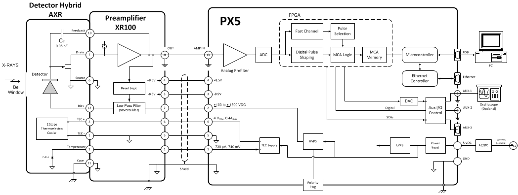
Amptek PX5 йҖЈжҺҘеңЁпјҲ1пјүеё¶еүҚзҪ®ж”ҫеӨ§еҷЁзҡ„ X е°„з·ҡе’ҢдјҪйҰ¬е°„з·ҡжҺўжё¬еҷЁе’ҢпјҲ2пјүйҒӢиЎҢж•ёж“ҡжҺЎйӣҶе’ҢжҺ§еҲ¶и»ҹй«”зҡ„иЁҲз®—ж©ҹд№Ӣй–“гҖӮ е®ғдё»иҰҒз”Ёж–јж”ҜжҸҙ Amptek XR-100 зі»еҲ—зҡ„ SDDгҖҒSi-PIN е’Ң CdTe жҺўжё¬еҷЁпјҢеҸҜиҲҮиЁұеӨҡе…¶е®ғиј»е°„жҺўжё¬еҷЁе’ҢеүҚзҪ®ж”ҫеӨ§еҷЁдёҖиө·дҪҝз”ЁпјҢеҢ…жӢ¬ HPGe жҺўжё¬еҷЁе’Ңй–ғзҲҚй«”жҺўжё¬еҷЁгҖӮ е®ғиҲҮд»»дёҖжҘөжҖ§зҡ„йҮҚзҪ®е’ҢеҸҚйҘӢеүҚзҪ®ж”ҫеӨ§еҷЁзӣёе®№гҖӮ PX5 еҢ…жӢ¬пјҲ1пјүй«ҳжҖ§иғҪж•ёдҪҚи„ҲиЎқиҷ•зҗҶеҷЁпјҲеҸ–д»ЈдәҶеӮізөұзҡ„ж•ҙеҪўж”ҫеӨ§еҷЁпјүгҖҒпјҲ2пјүеӨҡйҖҡйҒ“еҲҶжһҗе„Җе’ҢпјҲ3пјүдҪҺеЈ“е’Ңй«ҳеЈ“йӣ»жәҗпјҲ± HVпјүгҖӮ
иҲҮеӮізөұзі»зөұзӣёжҜ”пјҢPX5 е…·жңүеӨҡзЁ®е„ӘеӢўпјҢеҢ…жӢ¬ж”№йҖІзҡ„жҖ§иғҪпјҲи¶…й«ҳи§ЈжһҗеәҰгҖҒжӣҙе°‘зҡ„еҪҲйҒ“зјәйҷ·гҖҒжӣҙй«ҳзҡ„еӮійҒһйҮҸе’Ңеўһеј·зҡ„з©©е®ҡжҖ§пјүгҖҒжӣҙеӨҡз”Ёж–је„ӘеҢ–зі»зөұзҡ„й…ҚзҪ®йҒёй …д»ҘеҸҠиЁұеӨҡйҖҡдҝЎе’ҢијёеҮәйҒёй …гҖӮ PX5 еҹәж–ј Amptek жңҖж–°дёҖд»Јзҡ„ж•ёдҪҚи„ҲиЎқиҷ•зҗҶжҠҖиЎ“пјҢи©ІжҠҖиЎ“д№ҹз”Ёж–ј DP5 зі»еҲ—з”ўе“ҒгҖӮ
PX5 зҡ„дҝЎиҷҹијёе…ҘжҳҜеүҚзҪ®ж”ҫеӨ§еҷЁзҡ„ијёеҮәгҖӮ PX5 з”Ёж–је°ҮеүҚзҪ®ж”ҫеӨ§еҷЁијёеҮәж•ёдҪҚеҢ–пјҢе°ҚдҝЎиҷҹйҖІиЎҢеҚіжҷӮж•ёдҪҚиҷ•зҗҶпјҢжӘўжё¬еі°еҖјжҢҜе№…пјҲж•ёдҪҚпјүпјҢдёҰе°Үи©ІеҖје„ІеӯҳеңЁе…¶зӣҙж–№ең–иЁҳжҶ¶й«”дёӯпјҢеҫһиҖҢз”ҹжҲҗиғҪиӯңгҖӮ 然еҫҢпјҢиғҪиӯңйҖҡйҒҺ PX5 зҡ„ USBгҖҒд№ҷеӨӘз¶ІжҲ– RS-232 д»ӢйқўеӮіијёеҲ°з”ЁжҲ¶зҡ„йӣ»и…ҰгҖӮ
PX5 иҲҮ 32 дҪҚе’Ң 64 дҪҚдҪңжҘӯзі»зөұпјҲеҢ…жӢ¬ Windows 10пјүзӣёе®№гҖӮ
зү№й»һ- е–®еҖӢиЈқзҪ®иҲҮ當еүҚжүҖжңүзҡ„ Amptek SDDгҖҒSi-PIN е’Ң CdTe жҺўжё¬еҷЁзӣёе®№гҖӮ
- еҢ…жӢ¬ :
- ж•ёдҪҚи„ҲиЎқж•ҙеҪўж”ҫеӨ§еҷЁгҖӮ
- ж•ҙеҗҲеӨҡйҖҡйҒ“еҲҶжһҗе„ҖгҖӮ
- йӣ»жәҗгҖӮ
- ж”ҜжҸҙе…¶е®ғиЈҪйҖ е•Ҷзҡ„жҺўжё¬еҷЁд»ҘеҸҠд»»дёҖжҘөжҖ§зҡ„йҮҚзҪ®е’ҢеҸҚйҘӢеүҚзҪ®ж”ҫеӨ§еҷЁгҖӮ
- жўҜеҪўе’Ңж–°еһӢе°–еі°ж•ҙеҪўпјҢе…·жңүе»Јжіӣзҡ„еі°еҖјжҷӮй–“пјҢе°Үе…¶жҖ§иғҪжңҖдҪіеҢ–гҖӮ
- й«ҳиЁҲж•ёзҺҮиғҪеҠӣпјҢе…·жңүеҮәиүІзҡ„еҹәз·ҡз©©е®ҡжҖ§гҖҒеӮійҒһйҮҸе’Ңе Ҷз©ҚеҲӘйҷӨгҖӮ
- еӨҡйҒ”8kеҖӢијёеҮәMCAйҖҡйҒ“гҖӮ
- зӨәжіўеҷЁжЁЎејҸ – з”Ёж–ји„ҲиЎқзӣЈжё¬е’ҢиӘҝзҜҖзҡ„ DAC ијёеҮәгҖӮ
- 8 еҖӢе–®йҖҡйҒ“еҲҶжһҗе„ҖијёеҮәгҖӮ
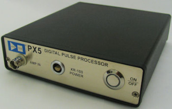
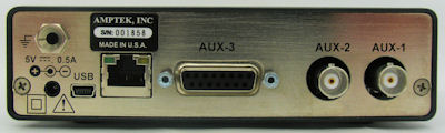
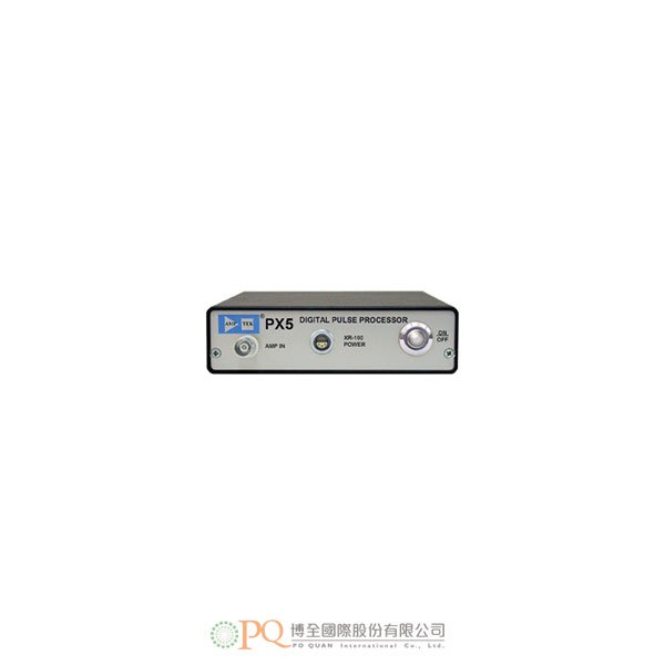
PX5 зҡ„жӯЈйқўе’ҢиғҢйқўең–иҰ–
PX5 йҖЈзөҗ XR-100SDD зҹҪжјӮ移жҺўжё¬еҷЁж–№еЎҠең–
еҰӮйңҖдәҶи§ЈжӣҙеӨҡдҝЎжҒҜпјҢи«Ӣз«ӢеҚіиҒҜ繫жҲ‘еҖ‘пјҒ
-
и„ҲиЎқиҷ•зҗҶжҖ§иғҪ
еўһзӣҠиЁӯзҪ®
зІ—иӘҝеўһзӣҠе’Ңеҫ®иӘҝеўһзӣҠзҡ„зө„еҗҲз”ўз”ҹдәҶеҫһ x0.75 еҲ° x516 йҖЈзәҢеҸҜиӘҝзҡ„зёҪеўһзӣҠгҖӮ
зІ—иӘҝеўһзӣҠ
еҫһ x1.00 еҲ° x413 зҡ„ 28 еҖӢе°Қж•ёй–“йҡ”зІ—иӘҝеўһзӣҠиЁӯзҪ®гҖӮ
еҫ®иӘҝеўһзӣҠ
еҸҜеңЁ 0.75 е’Ң 1.25 д№Ӣй–“иӘҝзҜҖпјҢ13 дҪҚи§ЈжһҗеәҰгҖӮ
йҮҸзЁӢ
1000 mV ијёе…Ҙи„ҲиЎқ @ x1 еўһзӣҠгҖӮ
еўһзӣҠз©©е®ҡжҖ§
<30 ppm/°CпјҲе…ёеһӢеҖјпјүгҖӮ
ADC жҷӮйҗҳй »зҺҮ
20 жҲ– 80 MHzпјҢ12 дҪҚ ADCгҖӮ
и„ҲиЎқеҪўзӢҖ
жўҜеҪўжҲ–е°–еі°гҖӮ е…·жңүж•ҙеҪўжҷӮй–“ t зҡ„еҚҠй«ҳж–Ҝж”ҫеӨ§еҷЁзҡ„еі°еҖјжҷӮй–“зӮә 2.4tпјҢе…¶жҖ§иғҪиҲҮзӣёеҗҢеі°еҖјжҷӮй–“зҡ„жўҜеҪўеҪўзӢҖзӣёз•¶гҖӮ
еі°еҖјжҷӮй–“
и»ҹй«”еҸҜйҒёзҡ„зҡ„еі°еҖјжҷӮй–“д»Ӣж–ј 0.05 е’Ң 102 μs д№Ӣй–“пјҢйҖҷе°ҚжҮүж–ј 0.04 иҮі 42.5 μs зҡ„еҚҠй«ҳж–Ҝж•ҙеҪўжҷӮй–“гҖӮ
е№ій ӮжҷӮй–“
жҜҸеҖӢеі°еҖјжҷӮй–“йғҪжңүдёҖдәӣи»ҹй«”еҸҜйҒёзҡ„еҖјпјҲеҸ–жұәж–јеі°еҖјжҷӮй–“пјүпјҢ>0.05 μs
жңҖеӨ§иЁҲж•ёзҺҮ
еі°еҖјжҷӮй–“зӮә 0.2 μs жҷӮпјҢеҸҜд»ҘжҺЎйӣҶеҲ° 4 MHz зҡ„е‘ЁжңҹдҝЎиҷҹгҖӮ
жҜҸеҖӢи„ҲиЎқзҡ„жӯ»еҚҖжҷӮй–“
1.05 еҖҚеі°еҖјжҷӮй–“гҖӮ з„ЎиҪүжҸӣжҷӮй–“гҖӮ
еҝ«йҖҹйҖҡйҒ“еі°еҖјжҷӮй–“
20 MHz: 200гҖҒ400гҖҒ800гҖҒ1600гҖҒ3200 nsгҖӮ
80 MHzпјҡ50гҖҒ100гҖҒ200гҖҒ400гҖҒ800 nsгҖӮеҝ«йҖҹйҖҡйҒ“и„ҲиЎқе°Қи§ЈжһҗеәҰ
1.2 x еҝ«йҖҹйҖҡйҒ“еі°еҖјжҷӮй–“пјҲжңҖе°Ҹ 60 nsпјүгҖӮ
е Ҷз©ҚеҲӘйҷӨ
и„ҲиЎқй–“йҡ”еӨ§ж–јеҝ«йҖҹйҖҡйҒ“еҲҶиҫЁжҷӮй–“е’Ңе°Ҹж–ј 1.05 x еі°еҖјжҷӮй–“зҡ„и„ҲиЎқе°Үиў«жӢ’зө•гҖӮ
еҹәз·ҡжҒўеҫ©
йқһе°ҚзЁұ – жңү 16 еҖӢи»ҹй«”еҸҜйҒёзҡ„иҪүжҸӣйҖҹзҺҮиЁӯзҪ®гҖӮ
дёҠеҚҮжҷӮй–“й‘‘еҲҘеҷЁпјҲRTDпјү
ж•ёеӯ—и„ҲиЎқиҷ•зҗҶеҷЁеҸҜзЁӢејҸиЁӯиЁҲзӮәж №ж“ҡе…¶дёҠеҚҮжҷӮй–“еұ¬жҖ§йҒёж“Үијёе…Ҙи„ҲиЎқгҖӮ
й–ҳ
й–ҳијёе…ҘиҲҮеӨ–йғЁйӣ»и·ҜдёҖиө·дҪҝз”ЁпјҢд»Ҙзўәе®ҡдәӢ件жҳҜеҗҰжҮүеҢ…жӢ¬еңЁе…үиӯңдёӯжҲ–еҫһе…үиӯңдёӯжҺ’йҷӨгҖӮ й–ҖеҸҜд»ҘзӮәй«ҳйӣ»е№іжңүж•ҲжҲ–дҪҺйӣ»е№іжңүж•ҲпјҲжҲ–иў«зҰҒз”ЁпјүгҖӮ
MCA жҖ§иғҪ
йҖҡйҒ“ж•ё
еҸҜзЁӢејҸиЁӯиЁҲзӮә 256гҖҒ512гҖҒ1kгҖҒ2kгҖҒ4K жҲ– 8k йҖҡйҒ“гҖӮ
жҜҸйҖҡйҒ“дҪҚе…ғзө„ж•ё
3дҪҚе…ғзө„пјҲ24 bitsпјүпјҢ16.7 M иЁҲж•ёгҖӮ
й җиЁӯж“·еҸ–жҷӮй–“
10 ms иҮі 466 еӨ©гҖӮ
ж•ёж“ҡеӮіијёжҷӮй–“
USBпјҡ1k йҖҡйҒ“ 4.8 ms; д№ҷеӨӘз¶Іи·Ҝ 1k йҖҡйҒ“ 35 msгҖӮ
иҪүжҸӣжҷӮй–“
з„Ў
й җиЁӯ
жҷӮй–“гҖҒзёҪиЁҲж•ёгҖҒROI иЁҲж•ёгҖҒйҖҡйҒ“иЁҲж•ёгҖӮ
MCS жҷӮеҹә
10 ms/йҖҡйҒ“иҮі 300 s/йҖҡйҒ“гҖӮ
еӨ–йғЁ MCA жҺ§еҲ¶
й–ҳијёе…Ҙпјҡ еҸӘжңүеңЁеӨ–йғЁйӮҸијҜй–ҳжҺ§жҷӮжүҚжҺҘеҸ—и„ҲиЎқгҖӮ ијёе…ҘеҸҜд»ҘжҳҜй«ҳйӣ»е№іжңүж•ҲжҲ–дҪҺйӣ»е№іжңүж•ҲгҖӮ
иЁҲж•ёеҷЁ
MCA жҺҘеҸ—зҡ„ж…ўйҖҹйҖҡйҒ“дәӢ件гҖӮ еӮіе…ҘиЁҲж•ёпјҲй«ҳж–јй–ҫеҖјзҡ„еҝ«йҖҹйҖҡйҒ“иЁҲж•ёпјүгҖҒйҒёж“ҮйӮҸијҜжӢ’зө•зҡ„дәӢ件е’ҢеӨ–йғЁдәӢ件иЁҲж•ёеҷЁгҖӮ
жё…е–®жЁЎејҸ
еҸ—ж”ҜжҸҙ
зЎ¬й«”
еҫ®иҷ•зҗҶеҷЁ
Silicon Labs 8051F340 8051зӣёе®№ж ёеҝғиҷ•зҗҶеҷЁгҖӮ
еӨ–йғЁиЁҳжҶ¶й«”
512 kb дҪҺеҠҹиҖ— SRAM
еӣә件
иЁҠиҷҹиҷ•зҗҶйҖҸйҒҺйҹҢй«”еҸҜзЁӢејҸеҢ–пјҢеҸҜеңЁзҸҫе ҙеҚҮзҙҡгҖӮ
йҖҡдҝЎ
RS-232
жЁҷжә–дёІиЎҢд»ӢйқўпјҢ115 жҲ– 56 KbaudгҖӮ
USB
жЁҷжә– 2.0 е…ЁйҖҹпјҲ12 MbpsпјүгҖӮ
д№ҷеӨӘз¶Іи·Ҝ
жЁҷжә– 10base-TгҖӮ
йҖЈжҺҘ
йЎһжҜ”ијёе…ҘпјҲBNCпјү
йЎһжҜ”ијёе…ҘжҺҘеҸ—дҫҶиҮӘйӣ»иҚ·йқҲж•ҸеүҚзҪ®ж”ҫеӨ§еҷЁзҡ„жӯЈеҗ‘жҲ–иІ еҗ‘и„ҲиЎқгҖӮ
йӣ»жәҗ
+5 VDCгҖӮ жҸ’й ӯиҲҮ 3.5 mm x 1.3 mm x 9.5 mm жҜҚй ӯзӯ’ејҸгҖҒдёӯеҝғжӯЈжҘөгҖҒжҸ’й ӯйҖЈжҺҘеҷЁй…ҚеҗҲдҪҝз”ЁгҖӮ
USB
жЁҷжә– USB mini-b жҸ’еӯ”гҖӮ
д№ҷеӨӘз¶Іи·Ҝ
жЁҷжә– RJ-45 д№ҷеӨӘз¶ІжҸ’еӯ”гҖӮ
AUX-1пјҲBNCпјү
еңЁи»ҹй«”дёӯй…ҚзҪ®зӮәпјҡпјҲ1пјүйЎһжҜ”ијёеҮәпјҢд»ҘжҹҘзңӢж•ҙеҪўи„ҲиЎқжҲ–иЁәж–·дҝЎиҷҹпјҢпјҲ2пјүж•ёдҪҚијёеҮәпјҢд»ҘжҹҘзңӢй‘‘еҲҘеҷЁијёеҮәжҲ–иЁәж–·дҝЎиҷҹжҲ–пјҲ3пјүж•ёдҪҚијёе…ҘгҖӮ
AUX-2пјҲBNCпјү
еңЁи»ҹй«”дёӯй…ҚзҪ®зӮәпјҲ1пјүж•ёдҪҚијёеҮәпјҢд»ҘжҹҘзңӢй‘‘еҲҘеҷЁијёеҮәжҲ–иЁәж–·дҝЎиҷҹжҲ–пјҲ2пјүж•ёдҪҚијёе…ҘпјҢд»Ҙй–ҳжҺ§жҲ–еҗҢжӯҘж•ёж“ҡж“·еҸ–гҖӮ
AUX-3пјҲ15 йҮқ D еһӢжҜҚй ӯйҖЈжҺҘеҷЁпјү
еҢ…жӢ¬пјҲaпјүдёІиЎҢ RS232 д»Ӣйқўз·ҡи·ҜпјҢпјҲbпјүеҸҜй…ҚзҪ®зӮәж•ёдҪҚијёе…ҘжҲ–ијёеҮәзҡ„е…©жўқз·ҡи·ҜпјҢ
пјҲcпјү8 еҖӢе–®йҖҡйҒ“еҲҶжһҗе„ҖпјҲSCAпјүијёеҮәе’ҢпјҲdпјүдёҖжўқз”Ёж–јйҒ з«ҜжҺ§еҲ¶йӣ»жәҗжү“й–ӢжҲ–й—ңй–үзҡ„жҺ§еҲ¶з·ҡи·ҜгҖӮXR-100 йӣ»жәҗпјҡ6 йҮқ Lemo йҖЈжҺҘеҷЁ
1
жә«еәҰ
2
еҒҸеЈ“пјҲжңҖй«ҳ ±1500V; жңҖеӨ§ 30 μAпјү
иӯҰе‘ҠпјҡдҪҝз”ЁйҢҜиӘӨзҡ„жҘөжҖ§жңғжҗҚеЈһжҺўжё¬еҷЁпјҢйҖҷзЁ®жҗҚеЈһдёҚеңЁдҝқдҝ®зҜ„еңҚе…§гҖӮ еңЁй–Ӣе•ҹ PX5 д№ӢеүҚпјҢи«ӢеӢҷеҝ…жӘўжҹҘжҳҜеҗҰиЁӯзҪ®дәҶжӯЈзўәзҡ„ HV жҘөжҖ§гҖӮ3
-8.5 жҲ– -5 VDCпјҲи»ҹй«”еҸҜйҒёпјү
4
+8.5 жҲ– +5 VDCпјҲи»ҹй«”еҸҜйҒёпјү
5
еҶ·еҚ»еҷЁ–пјҲжҺҘең°пјү
6
еҶ·еҚ»еҷЁ+пјҲйӣҷзҙҡеҶ·еҚ»еҷЁпјү
жҺҘең°е’ҢйҒ®зҪ©
йӣ»жәҗ
+5 V
500 mA жҷӮзӮә +5 VDCпјҲ2.5 WпјүпјҲе…ёеһӢеҖјпјүгҖӮ йӣ»жөҒеңЁеҫҲеӨ§зЁӢеәҰдёҠеҸ–жұәж–ј TdetпјҢ5 VDC жҷӮйӣ»жөҒд»Ӣж–ј 300 иҮі 800 mA д№Ӣй–“гҖӮ
ијёе…ҘзҜ„еңҚ
+4 V иҮі +5.5 VпјҲ0.4 иҮі 0.7 A е…ёеһӢеҖјпјү
еҲқе§Ӣзһ¬ж…Ӣ
2 AпјҢ<100 ns
иј”еҠ©ијёе…Ҙе’ҢијёеҮә
жӯӨйҖЈжҺҘеҷЁжңғијёеҮә PX5 дё»иҰҒеҠҹиғҪпјҲж“·еҸ–е…үиӯңдёҰйҖҡйҒҺдёІиЎҢд»ӢйқўеӮіијёпјүдёҚйңҖиҰҒзҡ„йӮҸијҜдҝЎиҷҹгҖӮ
йҖҷдәӣйҖҡеёёжҳҜиҲҮ PX5 иҷ•зҗҶзҡ„жҜҸеҖӢи„ҲиЎқзӣёй—ңзҡ„гҖҢдҪҺйӣ»е№ігҖҚйӮҸијҜдҝЎиҷҹ; з”Ёж–је°Ү PX5 иіҮж–ҷж“·еҸ–иҲҮеӨ–йғЁзЎ¬й«”еҗҢжӯҘд»ҘеҸҠз”Ёж–ј PX5 зҡ„зӣҙжҺҘиЁҲж•ёеҷЁ/е®ҡжҷӮеҷЁијёеҮәгҖӮ йҖҷдәӣдҝЎиҷҹеҰӮдёӢжүҖиҝ°гҖӮе–®йҖҡйҒ“еҲҶжһҗе„Җ
8 еҖӢ SCAпјҢзҚЁз«Ӣзҡ„и»ҹй«”еҸҜйҒё LLD е’Ң ULDпјҢLVCMOSпјҲ3.3 Vпјүйӣ»е№іпјҲTTL зӣёе®№пјүгҖӮ
ж•ёеӯ—ијёеҮә
2 еҖӢзҚЁз«ӢијёеҮәпјҢеҸҜйҖҡйҒҺи»ҹй«”еңЁ 8 зЁ®иЁӯзҪ®д№Ӣй–“йҒёж“ҮпјҢеҢ…жӢ¬ INCOMING_COUNTгҖҒPILEUPгҖҒMCS_TIMEBASE зӯүгҖӮ
LVCMOSпјҲ3.3 Vпјүйӣ»е№іпјҲTTL зӣёе®№пјүгҖӮж•ёеӯ—ијёе…Ҙ
2 еҖӢзҚЁз«Ӣијёе…ҘпјҢи»ҹй«”еҸҜйҒёж“Ү MCA_GATEгҖҒEXTERNAL_COUNTER
DAC ијёеҮә
з”Ёж–јзӨәжіўеҷЁжЁЎејҸпјҢд»ҘжҹҘзңӢж•ҙеҪўи„ҲиЎқе’Ңе…¶е®ғиЁәж–·дҝЎиҷҹгҖӮ зҜ„еңҚпјҡ0 иҮі 1 VгҖӮ
ж•ёдҪҚзӨәжіўеҷЁ
еңЁйӣ»и…ҰдёҠйЎҜзӨәзӨәжіўеҷЁжіўеҪўгҖӮ еҸҜи—үеҠ©и»ҹй«”йҒёж“ҮйЎҜзӨәж•ҙеҪўијёеҮәгҖҒADC ијёе…ҘзӯүпјҢд»Ҙ幫еҠ©иӘҝи©ҰжҲ–жңҖдҪіеҢ–й…ҚзҪ®гҖӮ
дёҖиҲ¬иіҮиЁҠе’Ңз’°еўғ
е·ҘдҪңжә«еәҰ
-40°C иҮі +85°CгҖӮ
дҝқеӣә
1 е№ҙ
е…ёеһӢиЁӯеӮҷеЈҪе‘Ҫ
5 иҮі 10 е№ҙпјҢиҰ–дҪҝз”Ёж–№ејҸиҖҢе®ҡгҖӮ
й•·жңҹеӯҳе„І
10 е№ҙд»ҘдёҠдҝқжҢҒз’°еўғд№ҫзҮҘгҖӮ
е…ёеһӢе„Іеӯҳе’ҢйҒӢијё
-40 °C иҮі +85 °CпјҢ10 иҮі 90% жҝ•еәҰпјҢз„ЎеҶ·еҮқ
еҗҲиҰҸ
з¬ҰеҗҲRoHSжЁҷжә–

TUV иӘҚиӯү
иӯүжӣёз·ЁиҷҹпјҡCU 72112987 01
經測и©Ұз¬ҰеҗҲпјҡUL 61010-1пјҡ 2004 R10.08
CAN/CSA-C22.2 61010-1-04+GI1 пјҲR2009пјүзү©зҗҶ
е°әеҜё
6.5 x 5.5 x 1.5 иӢұеҜё/165 x 135 x 40 mm
йҮҚйҮҸ
1.6 зЈ…/750 g
ж•ёдҪҚ I/Oпјҡ15 йҮқ D еһӢйҖЈжҺҘеҷЁпјҲжҜҚй ӯпјү
1
Gnd
2
RS232 – TX
3
RS232 -RX
4
SCA 6 ијёеҮә
5
SCA 5 ијёеҮә
6
Gnd
7
Aux 3
8
Aux 4
9
SCA 8 ијёеҮә
10
еӨ–йғЁйӣ»жәҗй–Ӣе•ҹ
11
SCA 7 ијёеҮә
12
SCA 1 ијёеҮә
13
SCA 2 ијёеҮә
14
SCA 3 ијёеҮә
15
SCA 4 ијёеҮә
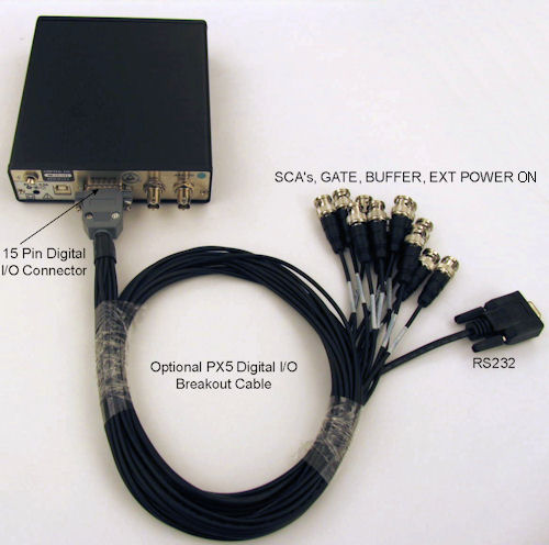
з”Ёж–ј PX5 зҡ„ 15 йҮқж•ёдҪҚијёе…Ҙ/ијёеҮәйӣ»зәңгҖӮйӣ¶д»¶з·Ёиҷҹ ACH-426гҖӮ
-
The Amptek PX5 interfaces between (1) an X-ray and gamma-ray detector with its preamplifier and (2) a computer running data acquisition and control software. Designed principally to support Amptek’s XR-100 series of SDD, Si-PIN, and CdTe detectors, it can be used with many other radiation detectors and preamplifiers, including HPGe detectors and scintillators. It is compatible with both reset and feedback preamplifiers of either polarity. The PX5 includes (1) a high performance digital pulse processor (replacing a conventional shaping amplifier), (2) a multichannel analyzer, and (3) both low and high voltage power supplies (±HV).
The PX5 offers several advantages over traditional systems, including improved performance (very high resolution, reduced ballistic deficit, higher throughput, and enhanced stability), many more configuration options to optimize the system, and many communications and output options. The PX5 is based on Amptek’s latest generation of digital pulse processing technology, also used in the DP5 family of products.
The signal input to the PX5 is the preamplifier output. The PX5 digitizes the preamplifier output, applies real-time digital processing to the signal, detects the peak amplitude (digitally), and bins this value in its histogramming memory, generating an energy spectrum. The spectrum is then transmitted over the PX5’s USB, Ethernet, or RS-232 interface to the user’s computer.
The PX5 is compatible with both 32 and 64 bit operating systems, including Windows 10.
Features- Single unit compatible with all current Amptek SDD, Si-PIN, and CdTe detectors
- Includes
- Digital pulse shaping amplifier
- Integrated multichannel analyzer
- Power supplies
- Supports detectors from other manufacturers, and both reset and feedback preamplifiers of either polarity
- Trapezoidal, and new Cusp shaping with wide range of peaking times to optimize performance
- High count rate capability with excellent baseline stability, throughput, and pile-up rejection
- Up to 8k output MCA channels
- Oscilloscope mode – DAC output for pulse monitoring and adjustment
- 8 single channel analyzer outputs
Front and back views of the PX5.
Figure 2. Block Diagram with PX5 and XR-100SDD Silicon Drift Detector
Contact us for more information today! -
Pulse Processing Performance
Gain Settings
Combination of coarse and fine gain yields overall gain continuously adjustable from x0.75 to x516.
Coarse Gain
28 log spaced coarse gain settings from x1.00 to x413.
Fine Gain
Adjustable between 0.75 and 1.25, 13 bit resolution.
Full Scale
1000 mV input pulse @ x1 gain.
Gain Stability
<30 ppm/°C (typical).
ADC Clock Rate
20 or 80 MHz, 12 bit ADC.
Pulse Shape
Trapezoidal or Cusp. A semi-gaussian amplifier with shaping time t has a peaking time of 2.4t
and is comparable in performance with the trapezoidal shape of the same peaking time.Peaking Times
Software selectable peaking times between 0.05 and 102 µs, corresponding to semi-Gaussian shaping times of 0.04 to 42.5 µs.
Flat Top Times
Software selectable values for each peaking time (depends on the peaking time), >0.05 µs.
Max Count Rate
With a peaking time of 0.2 µs, 4 MHz periodic signal can be acquired.
Dead Time per Pulse
1.05x peaking time. No conversion time.
Fast Channel Peaking Times
20 MHz: 200гҖҒ400гҖҒ800гҖҒ1600гҖҒ3200 nsгҖӮ
80 MHzпјҡ50гҖҒ100гҖҒ200гҖҒ400гҖҒ800 nsгҖӮFast Channel Pulse Pair Resolving Time
1.2 x Fast Channel Peaking Time (minimum of 60 ns)
Pile-Up Rejection
lses separated by more than the fast channel resolving time and less than 1.05x peaking time are rejected.
Baseline Restoration
Asymmetric – 16 software selectable slew rate settings.
Rise Time Discriminator (RTD)
The digital pulse processor can be programmed to select input pulses based on their rise time properties.
Gate
The gate input is used with external circuitry to determine if events should be included or excluded from the spectrum.
The gate can be active high or active low (or disabled).MCA Performance
Number of channels
Commandable to 256, 512, 1k, 2k, 4k, or 8k channels.
Bytes per channel
3 bytes (24 bits), 16.7 M counts.
Preset Acquisition Time
10 ms to 466 days.
Data Transfer Time
USB: 1k channels in 4.8 ms; Ethernet 1k channels in 35 ms
Conversion Time
None
Presets
Time, total counts, counts in an ROI, counts in a channel.
MCS Timebase
10 ms/channel to 300 s/channel.
External MCA Controls
Gate Input – Pulses accepted only when gated on by external logic. Input can be active high or active low.
Counters
Slow channel events accepted by MCA. Incoming counts (fast channel counts above threshold),
event rejected by selection logic, and external event counter.List Mode
Supported
Hardware
Microprocessor
Silicon Labs 8051F340 8051-compatible core.
External Memory
512 kb low-power SRAM
Firmware
Signal processing is programmed via firmware, can be upgraded in the field.
Communications
RS-232
Standard serial interface, 115 or 56 Kbaud.
USB
Standard 2.0 full speed (12 Mbps).
Ethernet
Standard 10base-T. -see app note
Connections
Analog Input (BNC)
The analog input accepts positive or negative going pulses from a charge sensitive preamplifier.
Power
+5 VDC. Plug mates with 3.5 mm x 1.3 mm x 9.5 mm female barrel, center positive, plug connector.
USB
Standard USB mini-b jack.
Ethernet
Standard RJ-45 Ethernet jack.
AUX-1пјҲBNCпјү
Configured in software as (1) an analog output, to view shaped pulses or diagnostic signals,
(2) a digital output, to view a discriminator output or diagnostic signals, or (3) a digital input.AUX-2пјҲBNCпјү
Configured in software as (1) a digital output, to view a discriminator output or diagnostic signals, or
(2) a digital input, to gate or synchronize data acquisition.AUX-3 (15 pin D connector female)
Includes (a) the lines for a serial RS232 interface, (b) two lines which can be configured for digital inputs or outputs,
(c) 8 single channel analyzer (SCA) outputs, and (d) a control line to command the power on or off remotely.XR-100 Power: 6-Pin Lemo Connector
1
Temperature
2
Bias (up to ±1500V; 30 µA maximum)
WARNING: Using the wrong polarity will destroy the detector and will NOT be covered under warranty.
Always check that the correct HV polarity is set before turning on the PX5.3
-8.5 or -5 VDC (software selectable)
4
+8.5 or +5 VDC (software selectable)
5
Cooler – (grounded)
6
Cooler + (2-stage cooler)
Ground on shield
Power
+5 V
+5 VDC at 500 mA (2.5 W) typical. Current depends strongly on Tdet, ranging from 300 to 800 mA at 5 VDC.
Input Range
+4 V to +5.5 V (0.4 to 0.7 A typical).
Initial Transient
2 AпјҢ<100 ns
Auxiliary Inputs and Outputs
The connectors bring out logic signals which are not required for the primary use of the PX5:
acquiring spectra and transmitting them over the serial interface.
These are generally “low level” logic signals associated with each pulse processed by the PX5;
used for synchronizing the PX5 data acquisition to external hardware and for direct counter/timer outputs from the PX5.
The signals are described below.Single Channel Analyzers
8 SCAs, independent software selectable LLDs and ULDs, LVCMOS (3.3 V) level (TTL compatible).
Digital Outputs
2 independent outputs, software selectable between 8 settings including
INCOMING_COUNT, PILEUP, MCS_TIMEBASE, etc. LVCMOS (3.3 V) levels (TTL compatible).Digital Inputs
2 independent inputs, software selectable for MCA_GATE, EXTERNAL_COUNTER.
DAC Output
Used in oscilloscope mode to view the shaped pulse and other diagnostic signals. Range: 0 to 1 V.
Digital Oscilloscope
Displays oscilloscope traces on the computer. Software selectable to show shaped output, ADC input, etc.,
to assist in debugging or optimizing configurations.General and Environmental
Operating Temperature
-40 °C to +85 °C.
Warranty Period
1 year
Typical Device Lifetime
5 to 10 years, depending on use.
Long-term Storage
10+ years in dry environment.
Typical Storage and Shipping
-40 °C to +85 °C, 10 to 90% humidity noncondensing
Compliance
RoHS Compliant
TUV CertificationCertificate #: CU 72112987 01
Tested to: UL 61010-1: 2004 R10.08
CAN/CSA-C22.2 61010-1-04+GI1 (R2009)Physical
Size
6.5” x 5.5” x 1.5” / 165 x 135 x 40 mm
Weight
1.6 lbs / 750 g
Digital I/O: 15 pin D connector (female)
1
Gnd
2
RS232 – TX
3
RS232 -RX
4
SCA 6 Out
5
SCA 5 Out
6
Gnd
7
Aux 3
8
Aux 4
9
SCA 8 Out
10
External Power On
11
SCA 7 Out
12
SCA 1 Out
13
SCA 2 Out
14
SCA 3 Out
15
SCA 4 Out
з”Ёж–ј PX5 зҡ„ 15 йҮқж•ёдҪҚијёе…Ҙ/ијёеҮәйӣ»зәңгҖӮйӣ¶д»¶з·Ёиҷҹ ACH-426гҖӮ
