


-
 AstroNova
-
 AOiP
AOiP
-
 ADASH
ADASH
-
 Amptek
-
 Automatic Research
-
 AWSensors
-
 AARONIA AG
-
 BASI
BASI
-
 CALMET
-
 DV Power
-
 DANATRONICS
-
 Dioxide Materials
-
 ED & D
-
 ELVEFLOW
-
 ECH
ECH
-
 Elsys
Elsys
-
 EA Technology
-
 Enapter
-
 Electrothermal
-
 Enervac
-
 EL-CELL
-
 ENERGY SUPPORT
-
 FASTEC
-
 GMW
GMW
-
 Gaskatel
-
 GIUSSANI
-
 Globecore
-
 GRZ
GRZ
-
 HVPD
HVPD
-
 HIGH SENSE SOLUTIONSHTW
-
 HUBER
HUBER
-
 IVIUM
IVIUM
-
 Ida
Ida
-
 Instytut Fotonowy
-
 JGG
JGG
-
 Jacomex
-
 Jenway
-
 Kocos
Kocos
-
 KEHUA TECH
-
 micrux
-
 Metrel
-
 Microrad
-
 METERTEST
-
 ndb
ndb
-
 Norecs
-
 Novocontrol
-
 Neware
-
 OKOndt Group
-
 OZM
OZM
-
 Pine Research
-
 Pinflow
-
 Redoxme
-
 SATIR
SATIR
-
 Sonel
Sonel
-
 Serstech
-
 SDT
SDT
-
 SENSIA
-
 SIKA
SIKA
-
 SMC
SMC
-
 TANDELTA
-
 TENTECH
-
 Turnkey Instruments
-
 VacCoat
-
 Zurich Instruments
- AstroNova
- AOiP
- ADASH
- Amptek
- Automatic Research
- AWSensors
- AARONIA AG
- BASI
- CALMET
- DV Power
- DANATRONICS
- Dioxide Materials
- ED & D
- ELVEFLOW
- ECH
- Elsys
- EA Technology
- Enapter
- Electrothermal
- Enervac
- EL-CELL
- ENERGY SUPPORT
- FASTEC
- GMW
- Gaskatel
- GIUSSANI
- Globecore
- GRZ
- HVPD
- HIGH SENSE SOLUTIONSHTW
- HUBER
- IVIUM
- Ida
- Instytut Fotonowy
- JGG
- Jacomex
- Jenway
- Kocos
- KEHUA TECH
- micrux
- Metrel
- Microrad
- METERTEST
- ndb
- Norecs
- Novocontrol
- Neware
- OKOndt Group
- OZM
- Pine Research
- Pinflow
- Redoxme
- SATIR
- Sonel
- Serstech
- SDT
- SENSIA
- SIKA
- SMC
- TANDELTA
- TENTECH
- Turnkey Instruments
- VacCoat
- Zurich Instruments
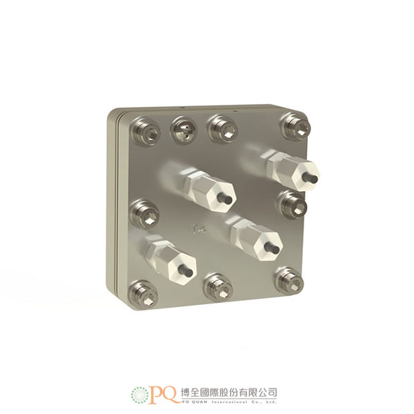

5 cm² CO2電解槽 (研究級硬體)
Complete 5 cm2 electrolyzer to convert CO2 to Formic Acid-
完整的 5 cm² CO2 電解槽。包括下列元件: 鈦陽極流場、904 L 不鏽鋼陰極流場、5 cm²電解槽陽極和陰極的催化劑包覆電極、Sustainion 膜、螺帽、螺栓、O 形環和絕緣套件,以及電解槽測試服務。
使用說明
DM鹼性CO2電解槽的初步建立系統設定(參考)
系統使用一台蠕動泵將 10mM KHCO3水溶液從儲液罐中以 3 mL/min 的流速迴圈至陽極流場。建議使用的管道為外徑 1/8 英寸,內徑 1/16 英寸的 PTFE 管道。使用瓶式加濕器(單獨出售)用水對來自鋼瓶的純CO2進行加濕,然後以30 sccm的流速將其送入陰極流場。
管路連接
陰極:從壓縮接頭上拆下螺母,並從螺母上拆下黑色橡膠棒,將 CO2加濕器的 PTFE 管(外徑 1/8 英寸)連接到陰極頂部的壓縮配件(不鏽鋼流場)上;將另一根 PTFE 管(外徑 1/8英寸)連接到陰極底部的壓縮接頭上,連接到陰極集液器,然後連接到排氣管。請注意,CO是有毒的,因此請勿將陰極產品氣體排放或釋放到實驗室或工作區域。
陽極:從壓縮接頭上拆下螺母,並從螺母上拆下黑色橡膠杆。然後將 PTFE 管(外徑 1/8英寸)推過螺母,將帶管的螺母轉動到底部的壓縮接頭上。將另一根 PTFE 管(外徑 1/8 英寸)連接到頂部的壓縮接頭上,並將其佈線回陽極液儲液罐中,僅用手指擰緊螺母。
電源連接
將用於接線的螺紋孔定位在單元頂部(較小的通孔 8-32 螺紋)。然後用8#十字圓頭螺釘連接環形端子。陽極和陰極使用相同的步驟。
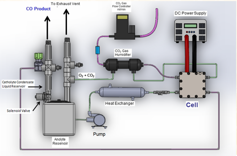
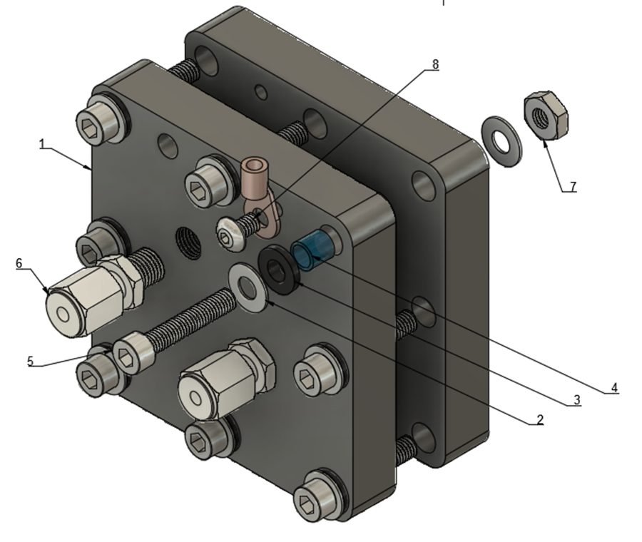
圖 1. 電解槽裝置 圖 2.5cm² 電解槽示意圖 電解槽測試和操作
首先以 3 mL/min 的速率將 10mM KHCO3水溶液從儲液罐泵送至陽極流場的入口(底部),並通過瓶式加濕器將 CO2注入陰極室的入口(頂部)。用電線/電纜(單獨購買)將陽極導線(紅色)和陰極導線(黑色)分別連接到電源的正極和負極連接上。測試開始時,將電源電壓設置為 3-3.2V,然後慢慢開始將電流增加到 1A(0.2A/cm2)。
電池電流將在幾分鐘或幾小時內達到所需的 1A,具體時間取決於離子膜和電極調節。也可以使用恆電位儀進行測試,但連接取決於測試步驟。 -
A complete 5 cm2 Formic Acid electrolyzer. Includes the following components: titanium anode flow field, central compartment, ion exchange media, 904 L stainless steel cathode flow field, catalyst covered electrodes for anode and cathode of 5 cm2 cell, Nafion® membrane, Sustainion® membrane, nuts, bolts, o-rings, gaskets, insulating kit, and electrolyzer testing service.
Description
This electrolyzer converts CO2 into formic acid. It uses a three-compartment design with a anode compartment, a center flow compartment containing a cation exchange media and a cathode compartment where the electrochemical reduction of CO2 to formic acid occurs.Instructions for use
Initial set up for DM Formic Acid ElectrolyzerSystem set up (recommended)
Typically, the system setup uses one peristaltic pump to circulate DI water (from the reservoir) into the anode chamber at a flowrate of 3 mL/min, and one peristaltic pump to feed DI water (from the reservoir) to the central compartment at a suggested flowrate of 0.065mL/min through the inlets located at the backside of the anode flow field. The flowrate of DI water into central compartment can be adjusted to vary the concentration of produced formic acid. Normally, a slow central compartment flowrate is in favor of the production of higher concentration of formic acid, with decreased Faradaic efficiency. The suggested tubing used is a 1/8” OD, 1/16” ID PTFE tubing. Pure CO2 from cylinder is humidified with water using a bottle humidifier (sold separately) and then fed to the cathode chamber at a flow rate of 30 sccm.
Tubing Connections- Cathode: remove the nuts from compression fittings and remove black rubber rods from the nuts. Push the tubing (1/8” OD, PTFE) through the nuts, turn the nuts with tubing inside onto the compression fittings. Connect the tubing (PTFE, 1/8”OD) from CO2 humidifier to the compression fitting at the top of cathode (stainless steel flow field), tighten the nuts with fingers only; Connect another tubing (PTFE, 1/8” OD) to the compression fitting at the bottom of cathode, route to the catholyte collector and then to THE EXHAUST. Please note that CO is poisonous and H2 is flammable, so please do not emit or release the cathode gas product into lab or working area.
- Anode: Remove the nuts from all the compression fittings and remove the black rubber rods from the nuts. Push the tubing (1/8” OD, PTFE) through the nuts, turn the nuts with tubing inside onto the compression fittings. Follow the labels of the compression fittings and connect all the tubing (1/8” OD, PTFE) accordingly. Tighten the nuts with fingers only.
Power Connections
Locate the threaded hole for wire connection on top of the cell (smaller through-hole 8-32 thread). Then connect the ring terminal with the Phillips round head screw (#8). Use this same procedure for both anode and cathode.
Figure 1. The electrolyzer setup Figure 2. Diagram of the 5 cm2 Formic Acid cell Cell Testing and Operation
Begin pumping DI water from reservoir to the inlet of the anode chamber at a rate of 3 mL/min and to the inlet of the central compartment at a flowrate of 0.065 mL/min, and feeding CO2 through a bottle humidifier to the inlet of the cathode chamber at a flowrate of 30 sccm. Connect the anode electrical lead (red) and cathode electrical lead (black) to the positive and negative connections, respectively, on the power supply with electric wires/cables (not included). Set the power supply voltage at 4.5 -5.0V and current at 0.5 A (0.1A/cm2) at the beginning of the testing. As the voltage decreases over time and stabilizes, progressively increase the current to 0.6A, 0.8A, 1.0A. The electrolyzer will reach stable conditions in several hours depending on the cell membrane and electrode conditioning. Testing can also be done with potentiostat, but the connections depend on the testing protocol. For long term testing, a reversed polarity treatment at 1.5 V for 30 second is recommended for every ~100 hours to maintain the cell performance.